Installation Instructions for use by heating contractor Vitocrossal 200 CM2 Series 400, 500, 620 and 620 TX Gas condensing boiler with cylinder burner Heating input: 1445 to 2245 MBH (423 to 658 kW) VITOCROSSAL 200 Product may not be exactly as shown IMPORTANT H 5584 069 - 05 09/2014 Read and save these instructions for future reference.
Safety Vitocrossal 200, CM2 400, 500, 620 and 620 TX Installation Safety, Installation and Warranty Requirements Please ensure that these instructions are read and understood before commencing installation. Failure to comply with the instructions listed below and details printed in this manual can cause product/property damage, severe personal injury, and/or loss of life. Ensure all requirements below are understood and fulfilled (including detailed information found in manual subsections).
Safety Vitocrossal 200, CM2 400, 500, 620 and 620 TX Installation Safety, Installation and Warranty Requirements Fiberglass wool and ceramic fiber materials WARNING Inhaling of fiberglass wool and/or ceramic fiber materials is a possible cancer hazard. These materials can also cause respiratory, skin and eye irritation. The state of California has listed the airborne fibers of these materials as a possible cancer hazard through inhalation. When handling these materials, special care must be applied.
Table of Contents Vitocrossal 200, CM2 400, 500, 620 and 620 TX Installation Page General Information Boiler 4 Safety, Installation and Warranty Requirements..............2 Product documentation.............................................2 Warranty................................................................2 Licensed professional heating contractor.....................2 Contaminated air.....................................................2 Advice to owner...........................................
Vitocrossal 200, CM2 400, 500, 620 and 620 TX Installation Table of Contents 5584 069 - 05 Page Venting General Venting Information......................................34 Installation steps (outline).......................................34 Recommended venting practice...............................34 Approved venting materials.....................................35 Vent termination location requirements (for installations in Canada).....................................
General Information Vitocrossal 200, CM2 400, 500, 620 and 620 TX Installation Important Regulatory and Installation Requirements For installations on the Commonwealth of Massachusetts, the following modifications to NFPA-54 chapter 10 apply: Excerpt from 248 CMR 5-08: 2(a) For all side-wall horizontally vented gas fueled equipment installed in every dwelling, building or structure used in whole or in part for residential purposes, including those owned or operated by the Commonwealth and where the side-
General Information Vitocrossal 200, CM2 400, 500, 620 and 620 TX Installation Important Regulatory and Installation Requirements For Polypropylene venting systems only Minimum and maximum wall thickness through which the horizontal vent-air intake termination may be installed: Minimum: 1 in. (25.4 mm) Maximum: 30 in. (762 mm) Vent-air intake system must be properly installed and sealed. If PP venting system passes through an unheated space, such as an attic, it must be insulated.
General Information Vitocrossal 200, CM2 400, 500, 620 and 620 TX Installation About these Installation Instructions Take note of all symbols and notations intended to draw attention to potential hazards or important product information. These include “WARNING”, “CAUTION”, and “IMPORTANT”. See below. WARNING Warnings draw your attention to the presence of potential hazards or important product information.
Vitocrossal 200, CM2 400, 500, 620 and 620 TX Installation General Information Mechanical Room The Vitocrossal 200, CM2 boiler should be located in a heated indoor space. The boiler should also be located near a floor drain and as close as possible to the vertical chimney or vent. Whenever possible, install boiler near an outside wall so that it is easy to duct fresh air directly to the boiler area. Install boiler on flooring capable of supporting the weight of the boiler filled with water.
Boiler Vitocrossal 200, CM2 400, 500, 620 and 620 TX Installation Recommended Minimum Service Clearances To enable convenient installation and maintenance, observe the stated clearance dimensions. Maintain the minimum clearances where space is tight. In the delivered condition, the boiler door hinge bracket is factory installed on the left side of the door. If required, the boiler door hinge bracket can be reinstalled on the right side of the door. CM2 a *1 b *2 in.
Boiler Vitocrossal 200, CM2 400, 500, 620 and 620 TX Installation Preparing the Boiler Note: To install lifting straps, use the lifting holes in the boiler end plates B. Observe the minimum clearances, see page 10. It is recommended that the boiler is to be installed on a concrete base. A recommended size of the concrete boiler base should be 50 in. (1250 mm) wide x 31 in. (800 mm) long x 4” (100 mm) thick for each boiler. WARNING . If flue gas connection is damaged leakage may occur.
Boiler Vitocrossal 200, CM2 400, 500, 620 and 620 TX Installation Boiler Insulation Remove all the components of the boiler jacket from the shipping box. 1. Wrap around the insulation blanket A (black nylon facing out) and look for boiler’s fitting cutouts. 2. Secure with spring clips. IMPORTANT The insulation blanket is not reversible. Ensure the correct orientation prior to installation. Boiler Door Insulation 1. Remove six boiler door bolts and set aside. 2. Swing the boiler door open. 3.
Vitocrossal 200, CM2 400, 500, 620 and 620 TX Installation Boiler Boiler Door Converting the boiler door 1. To convert the boiler door to the opposite side move hinge pin A to the RH side. Note: Ensure that sealing frame B presses onto the centre of gasket D in the boiler opening. It may be necessary to align mounting brackets C.
Boiler Vitocrossal 200, CM2 400, 500, 620 and 620 TX Installation Combustion Air Flex Hose 1. Attach the flex hose 7 8 in. (200 mm) to the flex hose adaptor and secure the flex hose to the flex hose adaptor with the retaining clamp. 2. Secure the flex hose to the support bracket with the retaining clamp. Note: Do not squeeze hose when securing it with the retaining clamp.
Boiler Vitocrossal 200, CM2 400, 500, 620 and 620 TX Installation Boiler Connections Water Side Connection Note: Make all connections free of load and torque stresses. The existing heating system must be properly flushed, especially if the Vitocrossal 200 boiler is connected to an existing heating system in a retrofit application. See page 9 for details. Connect the system to the boiler according the diagram on page 16.
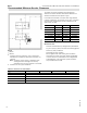
Boiler (continued) Legend 1 Boiler return: (ANSI 4 in.)* 2 Boiler supply: (ANSI 4 in.)* 3 Safety port (Safety valve, low water cutoff and automatic air vent) NPT 1a A Cross 1a in. B Hex bushing 1a in. x e in. C Air vent with shut-off base D Hex bushing 1a in. x c in. E 90° Street elbow 1 in. F Nipple 1 in. x 2 in. G Pressure relief valve, 75 psi H Low water cutoff 4 Pressure gauge fem. connection NPT b in. I Hex bushing b in. x a in.
Vitocrossal 200, CM2 400, 500, 620 and 620 TX Installation Boiler Hydrostatic Test Procedure All Vitocrossal boilers are factory tested (hydrostatic testing) to ASME requirements. The following testing procedure is to ensure that the boiler remained intact during shipping and handling. 1. Isolate boiler from hydronic heating system using isolating valves (i.e. expansion tank, feed water valve, pressure relief valve etc.). 2. Remove 75 psig pressure relief valve from the boiler and cap pipe outlet. 3.
Boiler Vitocrossal 200, CM2 400, 500, 620 and 620 TX Installation Rails and Supports 1. Insert four M6 x 10 screws halfway into each side of the top and base frame. 2. Hook the top LH and RH rails onto the top frame using the keyholes. 3. Hook the bottom LH and RH rails onto the base frame, so that the rails protrude to the rear. 4. Make sure the top rails are aligned at the front (see A). Then tighten all screws to secure each rail. 5. Install bottom plate brackets using two M6x15 screws per bracket.
Boiler Vitocrossal 200, CM2 400, 500, 620 and 620 TX Installation Cross Bar 1. Install the cross bar (using the rear holes) to the top rail with two screws. Mounting the Burner 1. Insert six M12 threaded studs into the boiler door. 2. Put gasket in place. 3. Position the burner at the boiler door, guiding the burner gauze assembly carefully through the opening. Note: Do not remove the burner gauze assembly protection during the installation to the boiler door.
Boiler Vitocrossal 200, CM2 400, 500, 620 and 620 TX Installation Combustion Air Adapter Burner Connection 1. Secure intake connector with hex head screws, washers and nuts to the flange of the rotary damper. 20 5584 069 - 05 2. Secure ventilation air hose DN 200 with hose clip 7 8 in. (7 200 mm) on the intake connector.
Vitocrossal 200, CM2 400, 500, 620 and 620 TX Installation Boiler Front Side Panels The gas train on the burner meets the requirement of ASME/CSD-1. 1. Cut out the aperture in front side panel either left or right. Note: For ease during burner maintenance, route the gas supply pipe from the opposite side of the burner hinges (otherwise the panel cannot be removed when swinging burner left or right). See page 13. 2. Fit two clips A per side panel (included in the accessory pack). 3.
Boiler Vitocrossal 200, CM2 400, 500, 620 and 620 TX Installation Electrical Connections Note: Never allow cables or leads to come into contact with hot components. Secure all cables and leads with cable ties. 1. Route the burner cables to the burner; apply strain reliefs or cable connectors as required. 2. Plug burner cable 41 and KM BUS cable 145 into the burner control unit. 3.
Vitocrossal 200, CM2 400, 500, 620 and 620 TX Installation Boiler Routing Cables 3A 3B Boiler water temperature sensor (supplied with the control unit) For installation see page 25. 15 Flue gas temperature sensor 40/156 Control unit connecting cable 41 Burner cable 145 KM BUS cable Note: Route 120 V cables F and low voltage leads separately. Route along the top rail A in a bundle using plug-in cable retainers. Route beneath the top B rail in a bundle using plug-in cable retainers.
Boiler Vitocrossal 200, CM2 400, 500, 620 and 620 TX Installation Boiler Water Temperature Sensor Note: The boiler water temperature sensor is located at the boiler supply connection. 1. Remove spring clip (set aside). 2. Insert 6 in. (150 mm) temperature sensor. 3. Observe the inserted depth. 4. Secure sensor lead with spring clip. 5. Insert the 3A and 3B plug to the burner electrical connector. Flue Gas Temperature Sensor and Pipe Coupling Connection 1.
Boiler Vitocrossal 200, CM2 400, 500, 620 and 620 TX Installation Condensate Connection 1. Fill the siphon with water and attach to boiler. IMPORTANT The condensate drain must be able to be inspected.
Boiler Vitocrossal 200, CM2 400, 500, 620 and 620 TX Installation Boiler Water Connection Temperature(continued) Sensor Condensate The Vitocrossal CM2 boiler comes with a built-in condensate trap (field installed). An external trap is not required when connecting the field drain to the P-trap. Discharge tubing (field supplied) must be 1 in. diameter. Use CPVC, PVC or other material approved by code listed below. The drain pipe and fittings must conform to ANSI standards and ASTM D1785 or D2846.
Vitocrossal 200, CM2 400, 500, 620 and 620 TX Installation Boiler Rear Panels 1. Install rear lower panel and secure with screws. 2. Install rear upper panel and secure with screws. 3. Install rear middle panel and secure with screws. Note: The gap in the middle rear panel is for inspection of the flue gas temperature sensor. Boiler Control and Junction Box 1. Install the junction box to the rear panel either right or left. Secure the junction box with four 4.8 mm metal screws. 2.
Boiler Vitocrossal 200, CM2 400, 500, 620 and 620 TX Installation Top Panels 1. Secure the front edge of central top panel A to the tie-bar with two 4.8 mm screws and secure the back of the panel to the LH and RH top rails with one 4.8 mm screw each. 2. Secure cover B to the tie-bar with two 4.8 mm screws. 3. Secure front top panel C to the front side panels with two M6 screws. 4. Position LH rear top panel D. Then position RH rear top panel E.
Boiler Vitocrossal 200, CM2 400, 500, 620 and 620 TX Installation Control Panel and Covers 1. Plug in control interface cable and install cover. 2. Install control cosmetic cover. 3. Install buffer panel to the top rail and secure with 4.8 mm metal screws. Legend A Control interface with cover B Buffer panel C Cosmetic cover Gas Flue Adaptor 1. Fully insert flue gas adapter inside the flue outlet (if used with stainless steel piping).
Boiler Vitocrossal 200, CM2 400, 500, 620 and 620 TX Installation Gas Connections The gas line on the burner meets the requirements of ASME/CSD-1. Note: For ease during burner maintenance, route the gas supply pipe from the opposite side of the burner hinges (otherwise the panel cannot be removed when swinging burner left or right). See page 13. 1. Connect gas pipe A to the gas valve. Gas connection: Boiler models 400, 500, 620 and 620 TX: 1¼ in. NPT 2.
Boiler Vitocrossal 200, CM2 400, 500, 620 and 620 TX Installation Gas Connections (continued) 1. Refer to current CAN/CSA B149.1 and .2 or National Fuel Gas Code ANSI Z223.1/NFPA 54, as well as local codes for gas piping requirements and sizing. Pipe size to the boiler must be determined based on: - pipe length - number of fittings - type of gas - maximum input requirements of all gas appliances in the residence.
Boiler Vitocrossal 200, CM2 400, 500, 620 and 620 TX Installation Boiler Piping in Heating / Cooling Application Heating / Cooling unit Heating / Cooling unit Heating / Cooling unit Water Chiller The boiler, when used in connection with a refrigeration system, must be installed so that the chilled medium is piped in parallel to the boiler and with appropriate valves to prevent the chilled medium from entering the boiler.
Boiler Vitocrossal 200, CM2 400, 500, 620 and 620 TX Installation Initial System Fill Treatment of boiler feed water should be considered in areas of known problems, such as high mineral content and hardness. In areas where freezing might occur, an antifreeze may be added to the system water to protect the system (maximum mix ratio - 50% / 50%). Please adhere to the specifications given by the antifreeze manufacturer for hydronic heating systems.
Venting Vitocrossal 200, CM2 400, 500, 620 and 620 TX Installation General Venting Information Installation steps (outline) WARNING Ensure that the entire venting system is protected from physical damages. A damaged venting system may cause unsafe conditions. WARNING The venting system is approved for indoor installations only. Do not install the venting system outdoors.
Venting Vitocrossal 200, CM2 400, 500, 620 and 620 TX Installation General Venting Information (continued) Approved venting materials Part Material Certified to Standards Applicability Exhaust pipe and fittings Stainless steel UL1738 “Venting systems for gas-burning appliances, Categories II, III, IV” U.S.A.
Venting General Venting Information Vitocrossal 200, CM2 400, 500, 620 and 620 TX Installation (continued) Vent termination location requirements (for installations in Canada) The vent must be installed observing local regulations in addition to National Codes, CAN/CSA-B149.1 or 2. The flexible vent pipe can only be used in vertical installations. A vent must NOT terminate... 1.....
Venting Vitocrossal 200, CM2 400, 500, 620 and 620 TX Installation General Venting Information (continued) Flashing and storm collar installation Flashings and storm collars are field supplied. Flashings and storm collars suitable for Type B vent materials (or better) may be used. To obtain flashings and storm collars, please contact your local vent material supplier. Follow the installation instructions supplied by the special venting manufacturer.
Venting Vitocrossal 200, CM2 400, 500, 620 and 620 TX Installation Requirement for UL/ULC Listed Rigid SS/PP(s) Vent Pipe Material The venting system must be installed in accordance with local building code requirements as well as national codes. For installations in Canada use CAN/CSA-B149.1 Natural Gas Installation Code or CAN/CSA-B149.2 Propane Installation Code as applicable; in the U.S. use the National Fuel Gas Code ANSI Z223.1 or NFPA Standard 54.
Venting Vitocrossal 200, CM2 400, 500, 620 and 620 TX Installation Vent Requirements Combustion air supply, room air dependent application only This boiler requires fresh air for safe operation and must be installed in a mechanical room where there are provisions for adequate combustion and ventilation air. Provisions for combustion and ventilation air must be made in accordance with CAN/CSA-B149.1 or .
Venting Vitocrossal 200, CM2 400, 500, 620 and 620 TX Installation Direct Venting (Two Pipe System) Side wall vent termination (stainless steel, CPVC or PP) IMPORTANT Stainless steel or plastic mesh The exhaust vent/air intake system must terminate so that proper clearances are maintained as cited in local codes or the latest edition of the “Natural Gas and Propane Installation Code” CAN/CSA-B149.1 (Canada), or the “National Fuel Gas Code” ANSI Z223.1 (NFPA 54) (U.S.A.). Min. 26 in.
Venting Vitocrossal 200, CM2 400, 500, 620 and 620 TX Installation Side Wall Venting Side wall vent termination (stainless steel or PP) IMPORTANT For PP systems, all exhaust vent and air intake piping and elbows exposed outside, must be UV resistant polypropylene (supplied by the vent manufacturer). Min. 12 in. (305 mm) Exhaust vent terminal 90o Grade or max. snow level Min. 2 in. (50 mm) Max. 36 in. (915 mm) Flue Support bracket Termination elbow with screen Side wall Max. 36 in.
Venting Vitocrossal 200, CM2 400, 500, 620 and 620 TX Installation Component Installation Guide Flashing and storm collar installation Flashings and storm collars are field supplied. Flashings and storm collars suitable for Type B vent materials (or better) may be used. To obtain flashings and storm collars, please contact your local vent material supplier. Follow the installation instructions supplied by the special venting manufacturer.
Venting Vitocrossal 200, CM2 400, 500, 620 and 620 TX Installation Installation of Support System - PP Bracing Contact your local vent material supplier for more information specific to your installation. Braces are required to stabilize an installation. There are different types and their use and spacing vary. IMPORTANT For exhaust vent pipe material: Use only ULC S-636 / UL 1738 vent material.
Venting Options - Stainless Steel / PP Vitocrossal 200, CM2 400, 500, 620 and 620 TX Installation Two Pipe System - Vertical Exhaust / Vertical Air Intake Flue Air a - Equivalent length (exhaust) b - Equivalent length (air intake) 44 5584 069 - 05 Note: See table on page 47.
Vitocrossal 200, CM2 400, 500, 620 and 620 TX Installation Venting Options - Stainless Steel / PP Two Pipe System - Vertical Exhaust / Vertical Air Intake IMPORTANT All PP(s) vent termination elbows, must be secured in place as specified by manufacturer. IMPORTANT For PP(s) systems, all exhaust vent and air intake piping and elbows exposed outside, must be UV resistant polypropylene (supplied by the vent manufacturer).
Venting Options - Stainless Steel / PP Vitocrossal 200, CM2 400, 500, 620 and 620 TX Installation Two Pipe System - Horizontal Exhaust / Horizontal Air Intake Flue Min. 24 in. (610 mm) Air 46 5584 069 - 05 a - Equivalent length (exhaust) b - Equivalent length (air intake) Note: See table on page 47.
Venting Options - Stainless Steel / PP Vitocrossal 200, CM2 400, 500, 620 and 620 TX Installation Two Pipe System - Vertical Exhaust / Horizontal Air Intake Flue Air a - Equivalent length (exhaust) b - Equivalent length (air intake) Note: See table below. Two Pipe System - Vertical / Horizontal Installations Maximum allowable equivalent length - Stainless steel / PP Boiler Models CM2 400, 500, 620 and 620 TX Flue gas combustion air in. (mm) in. (mm) Max. equivalent length a+b [ft.
Venting Options - Stainless Steel / PP Vitocrossal 200, CM2 400, 500, 620 and 620 TX Installation Single Pipe System - Vertical Exhaust / Room Air Dependant Flue Combustion Air Opening a - Equivalent length (exhaust) Note: See table on page 49. Air Single Pipe System - Horizontal Exhaust / Room Air Dependant Air 48 Flue a - Equivalent length (exhaust) Note: See table on page 49.
Vitocrossal 200, CM2 400, 500, 620 and 620 TX Installation Venting Options - Stainless Steel / PP Single Pipe System - Vertical / Horizontal Installations Maximum allowable equivalent length - Stainless steel / PP Boiler Models CM2 400, 500, 620, and 620 TX Flue gas combustion air in. (mm) in. (mm) Max. equivalent length a+b [ft.
5584 069 - 05 Vitocrossal 200, CM2 400, 500, 620 and 620 TX Installation
5584 069 - 05 Vitocrossal 200, CM2 400, 500, 620 and 620 TX Installation 51
5584 069 - 05 Technical information subject to change without notice. Printed on environmentally friendly (recycled and recyclable) paper.