VITOGAS 100 Low-temperature gas-fired boiler 72 to 144 kW as multi-boiler systems up to 432 kW File in: Vitotec technical guide folder, register 2 Technical guide Design and operation 5822 239-1 GB 2/2002
Contents Contents 1 Specification Page 1.1 Product information and operating conditions . . . . . . . . . . . . . . . . . . . . . . . . . . . . . . . . . . . . . . . . . . . . . . . . . . . . . . . . . . . . . 1.2 Boiler control units and control panels H For the operation of single boiler systems . . . . . . . . . . . . . . . . . . . . . . . . . . . . . . . . . . . . . . . . . . . . . . . . . . . . . . . . . . . . . . . . . H For the operation of multiple boiler systems . . . . . . . . . . . . . . . . .
1.1 Product information and operating conditions 1.
1.2 Boiler control units 1.
1.2 Boiler control units 2.
2.1 Design in general Location General requirements The boiler location should meet the Combustion Regulation standards set by the respective country. In rooms where air contamination through halogenated hydrocarbons may occur, such as in hairdressing salons, printing shops, chemical cleaners and laboratories, boilers may only be installed if adequate measures can be taken to provide uncontaminated combustion air. If in doubt, please contact us.
2.1 Design in general 2.2 Water connection System design Flow temperatures To keep distribution losses to a minimum, we recommend that the H heat distribution system and the H domestic hot water heating are designed for a max. of 70 ºC (flow temperature). For boilers supplied with a boiler control unit, limit the max. boiler water temperature to 87/95 ºC. Changing the control thermostat can increase the flow temperature. Selection of the rated output Select boilers acc. to the required heat demand.
2.3 Safety equipment 2.3 Safety equipment acc. to DIN 4751-2 DIN 4751-2 applies to the design, installation and operation of sealed and thermostatically protected heat generator systems for hot water with permissible flow temperatures of up to 100 ºC in water-filled heating systems. Safety equipment acc. to DIN 4751-2 This standard contains safety requirements laid down for heat generators and heat generator systems.
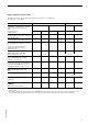
2.3 Safety equipment Safety equipment selection table This table indicates the safety equipment required for each system acc. to DIN 4751-2.
2.4 Flue gas connection 2.4 Flue gas connection Flue gas connection CE certified flue gas collectors are located on the flue side of boilers. Each boiler is equipped with its own draught hood. For multi-boiler systems, the flue gas collector is part of the standard delivery, see price list for details. Implement the ventilation and extraction system for boiler rooms in accordance with the Combustion Regulation of the individual state as well as TRGI ’86/96 or TRF 1996.
2.5 Flue gas re-circulation 2.5 Flue gas re-circulation Sizing the flue gas system Calculating the cross-sections of the flue gas system is the basis of and a pre-requisite for the proper function of any flue gas system. You can determine the cross-section of the flue gas system depending on the rated output and the effective height of the flue gas systems using the following cross-section diagram. DIN 4705 was taken into consideration in calculating the cross-section diagram.
2.6 Gas connection 2.7 Electrical connection 2.6 Gas connection Gas installations should only be carried out by an approved installer, who has been authorised by the relevant gas supplier. Connect the mains gas acc. to TRGI ’86/96 or TRF 1996. Max. test pressure 150 mbar. We recommend the installation of a gas filter acc. to DIN 3386 into the gas supply line. Thermal safety shut-off valve According to. paragraph 4, sect.
2.8 Standard values for water quality 2.8 Standard values for water quality The service life of the heat generator and the complete heating system is influenced by the water conditions. In any event, the cost of a water treatment facility is less than the cost of repairing defects on your heating system. It is necessary to maintain the following requirements to safeguard your warranty rights. The manufacturer’s warranty excludes damage due to corrosion and scaling.
3.
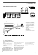
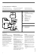
3.1 Application example 1 Installation diagrams A 52 2 1 20 M2 1 M2 2 3 90 41 40 2 20 2 52 1 A 5 28 52 2 20 M2 21 1 M2 2 2 3 90 41 40 1 28 21 20 2 52 5 1 2 B 5822 239 Plug-in connector ! Outside temperature sensor*1 ? M2 Flow temperature sensor mixer*1 § Boiler temperature sensor % DHW cylinder temperature sensor sÖ M2 Heating circuit pump mixer*1 A B Heating circuit with mixer Domestic hot water cylinder *1Only for Vitotronic 200 (type KW2).
3.1 Application example 2 Application example 2 - Single boiler system with Vitogas 100 boiler and one heating circuit with mixer and system separation System: Single boiler system with H Vitogas 100 (72 to 144 kW) H Vitotronic 200 (type KW2) or Vitotronic 100 (type GC1) with Vitocontrol control panel and integrated weather-compensated Vitotronic 333 (type MW1S) control unit or Vitotronic 100 (type KC2) and external, weather-compensated control unit (for connections, see page 42) H 3-way mixer.
3.1 Application example 2 Installation diagram 52 2 1 20 M2 M2 2 A 3 3 90 41 40 1 2 52 20 2 1 5822 239 Plug-in connector ! Outside temperature sensor*1 ? M2 Flow temperature sensor mixer*1 § Boiler temperature sensor A Underfloor heating circuit *1 Only for Vitotronic 200 (type KW2). 4 sÖ M2 Heating circuit pump mixer*1 fÖ Electrical mains connection, 230V~/50 Hz Install the mains isolator according to local regulations.
3.
3.
3.
3.
3.
3.
3.
3.1 Application example 6 Wiring diagram Connection of the temperature sensor or limit thermostat T1 H in conjunction with Vitotronic 300 (type GW2) H in conjunction with Vitotronic 100 (type KC2) Wiring for reducing the volume flow via the limit thermostat T1 in heating systems with heating circuit control units, which are not connected to the boiler control unit via the LON BUS. Necessary coding: change ”4C” to ”2” – use the plug-in connector sÖ A1 to close the downstream mixer.
3.1 Application example 6 Equipment required (For standard systems – equipment with additional system modules, see Vitotec 2 folder) Description Number Part no. 1 Boiler with Vitotronic 1 as per price list 2 Temperature sensor T2 (in conjunction with Vitotronic 300 (type GW2) – Contact temperature sensor or – Immersion temperature sensor (incl.
3.
3.
3.
3.
3.
3.
3.
3.
3.
3.
3.
3.
3.
3.2 Domestic hot water heating with cylinder loading system 3.2 Domestic hot water heating with cylinder loading system The Viessmann cylinder loading system is a combination of a Vitocell-L cylinder and a Vitotrans heat exchanger set. The cylinder loading system for DHW heating is a preferred choice for: H large storage capacities with offset loading and drawing times, e.g. water is drawn off in bursts at schools, sports centres, hospitals, army camps, social buildings, etc. H short-term peak loads, i.e.
3.2 Domestic hot water heating with cylinder loading system Notes regarding the application examples (chapter 3.1) Application example 6 The sensor input aJ B is used to control the Vitotrans 222 heat exchanger set. Therefore, the shunt pump must be controlled by a separate thermostat (see figure adjacent). L1 N PE A B C A Connection box, on site B Shunt pump C Limit thermostat, part no.
3.3 Installation notes 3.3 Installation notes Connection of an on-site control unit to Vitotronic 100 (type KC2) – single boiler systems Operation with a two-stage burner Plug-in connectors inside the control unit 150 STB PE N STB TR TR ON ON Volt-free contacts of the overriding control units: Remove the wire jumper from the plug-in connector a-D. Settings on Vitotronic 100 The high limit safety cut-out settings and other settings depend on the system equipment and the safety equipment acc.
3.3 Installation notes Connection of an on-site control unit to Vitotronic 100 (type KC2) – multi-boiler systems Operation with a two-stage burner Plug-in connectors inside the control unit 150 STB PE N STB TR TR ON ON Volt-free contacts of the overriding control units: Remove the wire jumper from the plug-in connector a-D. The contact ”enable boiler” must be constantly closed at the lead boiler and closed on demand at the lag boiler.
3.3 Installation notes Additional connection options H to Vitotronic 200 (type KW2) Additional connections to Vitotronic 200 (type KW2) are possible in conjunction with the switching module V (part no. 7143 513) (see installation instructions for switching module V).
3.3 Installation notes Change of external heating program/mixer open Also applicable to Vitotronic 050 The manually pre-selected heating program can be changed or the connected mixer can be opened via the volt-free plug-in connection aVD terminals ”1” and ”2”.
3.3 Installation notes Connection to the external changeover facility The connection is made on site via terminals ”1” and ”2” of the plug-in connector aVH. 143 1 2 3 146 1 2 3 External request External blocking/close mixer External heating program changeover/ open mixer H to Vitotronic 100 (type GC1) in conjunction with Vitotronic 333 (type MW1) Volt-free contacts: Block boiler Start boiler as the last one in the boiler sequence 143 Contact closed: The boiler is blocked.
3.3 Installation notes 3.4 On-site control equipment via LON BUS Electrical connection of a motorised flue gas damper 150 STB PE N STB TR TR ON ON 1 1 2 3 Si Flue gas damper motor *1 remove b) the wire jumper Plug-in adaptor for external safety equipment Several additional pieces of safety equipment may be connected: H Low water indicator H Minimum pressure limiter H Maximum pressure limiter H Additional high limit safety cut-out and 3 external fault messages (e.g. pump or neutralisation system).
4.1 Index 4.1 Index B P Boiler control units, 4 Positioning, 5 C Product information, 3 Chimney diagram, 11 R Combustion air supply, 6 Requirements of the heating water, 13 Control panels, 4 S Corrosion on the primary side (avoidance), 13 Safety temperatures, 7 Safety valve, 8 Cylinder loading system, 40 Sizing, 7 D Standard efficiency, 3 Delivery, 5 Switching points, 5 Printed on environmentally friendly, chlorine-free bleached paper.