
Datasheet


5822 239
G
B
8
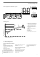
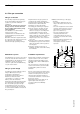
2.3 Safety equipment
2.3 Safety equipment acc. to DIN 4751-2
DIN 4751-2 applies to the design,
installation and operation of sealed and
thermostatically protected heat generator
systems for hot water with permissible
flow temperatures of up to 100 ºCin
water-filled heating systems.
This standard contains safety
requirements laid down for heat
generators and heat generator systems.
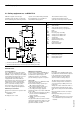
Safety equipment acc. to DIN 4751-2
Required safety equipment
1
ADG Sealed expansion vessel
AV1 Shut-off valve
AV2 Shut-off valve (protected against
unintentional closing, e.g. cap valve)
EDrain
EST Flash trap
MA Pressure gauge assembly
SDB1 Safety pressure limiter max.
SDB2 Safety pressure limiter min.
SIV Safety valve
SL Safety expansion pipe
STB High limit safety cut-out
TH Thermometer
TR Control thermostat
WB Water level limiter
2
Further legends
1 Delivered with Viessmann maxi mum pressure limiting assembly
2 Delivered with Viessmann minimum pressure limiting assembly
2
HK Heating circuit
HKP Heating circuit pump
HR Heating water return
HV Heating water flow
General notes
Low water indicator
Acc. to DIN 4751-2, a special low water
indicator can be omitted for boilers up to
350 kW, a s long as heating can be reliably
stopped when the water level is too low.
Viessmann Vitogas 100 boilers are
equipped with a low water indicator
(boil-dry protection). Tests have verified
that the burner will be automatically
switched off in case of water shortage,
due to a leak in the heating system,
before the boiler or flue gas systems
reach unacceptably high temperatures.
Maximum pressure limiter
Required for each boiler in systems with
a
H rated boiler output
> 350 kW or a
H safety pressure > 3 bar.
Minimum pressure limiter
Required in accordance with DIN 4751-2
in case of safety temperatures > 100 ºC
(install into the expansion pipe). In
multi-boiler systems, one minimum
pressure limiter per system is required.
Safety valve
Equip the boilers acc. to DIN 4751-2 with
a type-tested safety valve
H for hot water heating systems up to
100 ºC flow temperature and
H for hot water heating systems up to
120 ºC flow temperature as well
as according to their type approval.
Identify this valve in accordance with TRD
721, i.e. with
H ”H” up to 3.0 bar permissible operating
pressure and max. 2700 kW rated
output, and with
H ”D/G/H” for all other operating
conditions.
The pipework between the boiler and the
safety valve should not be able to be shut
off. Pumps, fittings or restrictions in this
pipework should be avoided.
Flash trap
For boilers above 350 kW, install a flash
trap with blow-off and drain line adjacent
to the safety valve. The blow-off line
should lead outdoors. Any expelled
steam should not endanger anyone.
The blow-off line from the safety valve
should be designed and constructed so
as to prevent the possibility of increases
in pressure.
Arrange the outlet of the blow-off line so
that any water expelled from the safety
valve can be safely observed and drained
off.
Flash trap and blow-off line can only be
omitted, if
H the high limit safety cut-out is set to
100 ºC, and
H a second high limit safety cut-out and a
second maximum pressure limiter are
installed.