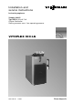
Installation and service instructions for heating engineers Vitoplex 100−LS Type SXD, 0.26 to 0.
General information Safety instructions Please follow these safety instructions closely to prevent accidents and material losses. In an emergency H Immediately switch OFF emergency stop switch (outside boiler room) (except if you smell gas). H Close the shut−off valves of the main fuel lines. H For fire, use an appropriate fire extinguisher.
Contents Index Page General information Safety instructions . . . . . . . . . . . . . . . . . . . . . . . . . . . . . . . . . . . . . . . . . . . . . . . . . . . . . . . . . . . . . . . . . . . . . . . . . . . . . . . . . . . . . . . . . . . . . . . . . . . . . . . . . . . . . . . . . . Notice of completion . . . . . . . . . . . . . . . . . . . . . . . . . . . . . . . . . . . . . . . . . . . . . . . . . . . . . . . . . . . . . . . . . . . . . . . . . . . . . . . . . . . . . . . . . . . . . . . . . . . .
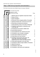
Initial start−up, inspection and maintenance Steps initial start−up, inspection and maintenance For further instructions on individual steps, see pages indicated. Commissioning steps Inspection steps Maintenance steps C C I I I I M M M M M M M M 1. Adjusting pressure regulator and pressure limiter M M M M M M M 9. Checking thermal insulation of boiler door M M M M M ..... 6 2. System start−up . . . . . . . . . . . . . . . . . . . . . . . . . . . . . . . . . . . . . . . . . . . . . . . . . .
Initial start−up, inspection and maintenance Steps initial start−up, inspection and maintenance (cont.) Commissioning steps Inspection steps Maintenance steps M 21. Checking the pressure regulator, pressure limiter and thermostat (standby) . . . . . . . . . . . . . . . . . . . . . . . . . . . . . . . . . . . . . . . . . . . . . . . . . . . . . . . 17 M M M M 22. Checking the water quality . . . . . . . . . . . . . . . . . . . . . . . . . . . . . . . . . . . . . . . . . . . . . . . . . . . . 26 23.
Initial start−up, inspection and maintenance Further details regarding the individual steps Maintenance instructions We recommend that your boiler system is maintained regularly by a heating specialist to ensure fault−free, energy−conscious and environmentally safe operation of your heating system. Your boiler must be cleaned at regular intervals, otherwise the flue gas temperature rises with increasing contamination, which leads to higher energy losses. We recommend the use of a flue gas thermometer.
Initial start−up, inspection and maintenance Further details regarding the individual steps (cont.) According to the [German] Health & Safety at Work Act, steam boilers with a safety pressure in excess of 0.5 bar must be monitored. In accordance with the conformity assessment diagram no. 5 of the EU Pressure Equipment Directive, these boilers must be categorised as class III. Prior to commissioning, this system must be tested by an authorised body (e. g. TÜV).
Initial start−up, inspection and maintenance Further details regarding the individual steps (cont.) System shutdown ¨ Safety instruction Only open the water and steam connections and the inspection ports after the boiler has been completely depressurised. 1. Close the shut−off valves in the oil supply pipes (at the oil tank and filter) or the gas shut−off valve, whichever is applicable. 2. Switch OFF the burner and the feed water pump. Pull the connecting plug from the burner. 3.
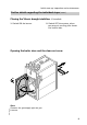
Initial start−up, inspection and maintenance Further details regarding the individual steps (cont.) Closing the Vitoair draught stabiliser (if installed) 1. Switch ON the burner. 2. Switch OFF the system, when pre−purge is running; this closes the control disc. Opening the boiler door and the clean−out cover 5692 729 GB 4x Note Remove the gas supply pipe on gas burners.
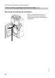
Initial start−up, inspection and maintenance Further details regarding the individual steps (cont.) Removing and cleaning the turbulators Remove turbulators A without force; for this, use the turbulator pulley, which is part of the cleaning equipment.
Initial start−up, inspection and maintenance Further details regarding the individual steps (cont.) Clean the heating surface, flue outlet and flue pipe 1. Clean flues A and combustion chamber B with brushes and remove combustion residues. A B 5692 729 GB 2. Remove combustion residues from the flue pipe and the flue outlet C.
Initial start−up, inspection and maintenance Further details regarding the individual steps (cont.) Inserting the turbulators ¨ Burner adjustments and specific system conditions can lead the turbulators to move forward, which may result in them being burnt. The thermal insulation on the boiler door can also be damaged by this. A B 1. Pull approx ¾ of the length of turbulators A out of secondary heating pipes B. 2. Bend turbulators approx. 10 15º. 3.
Initial start−up, inspection and maintenance Further details regarding the individual steps (cont.) Securing the boiler door and clean−out cover Note Refit the gas supply pipe on gas burners. ¨ Safety instruction Carry out a leak test on all gas supply connections. A 4x 5692 729 GB A Tighten the screws diagonally.
Initial start−up, inspection and maintenance Further details regarding the individual steps (cont.) Checking the water chamber for deposits A 1. Open hand hole cover A. 2. Fully drain the boiler. 3. Clean the water chamber (hose it out) and remove deposits via the blow−down valve and drain. In case of harder deposits which cannot be removed by hosing down, carry out a chemical cleaning process using added descaler. 5692 729 GB 4. Clean all sealing faces on closures, and replace gaskets, where required.
Initial start−up, inspection and maintenance Further details regarding the individual steps (cont.) Cleaning the multiple level electrode 1. Remove electrode A. A 2. Clean electrode tips C. B 3. Clean the sealing faces and use a new gasket B. C 4. Install the electrodes and carry out a safety test in line with the manufacturer’s instructions. 5. Retighten new gaskets after commissioning. Cleaning the water level indicator 1. Blow out the water level indicator. 2.
Initial start−up, inspection and maintenance Further details regarding the individual steps (cont.) Checking all connections at the water and steam sides, the sensor well and the inspection ports for leaks after filling the boiler Each time inspection ports have been opened: 1. Clean the sealing surface. 2. Replace the gasket. A 3. Retighten all connections after restarting the system. For testing the sensor well, remove cover A.
Initial start−up, inspection and maintenance Further details regarding the individual steps (cont.) Checking the Vitoair draught stabiliser (if installed) Release the latch on the control disc. The control disc must swing freely during burner operation. Adjusting the burner Burner manufacturer’s details During adjustments, observe the minimum output. Set the minimum heating output for the base load stage according to the chimney conditions.
Troubleshooting Diagnostics Fault/ system characteristics Cause Remedy Burner does not start No voltage Switch ON the mains electrical isolator Safety chain activated Check all safety equipment Burner fault indicator illuminates Press the reset button at the burner control unit Fuel supply interrupted Open the shut−off valves in the fuel supply line and filter Remedy other faults in accordance with the burner manufacturer’s instructions Oxygen corrosion (water side) Topping up with unsuitable
Troubleshooting Diagnostics (cont.) Fault/ system characteristics Cause Remedy The boiler produces wet steam The boiler water alkalinity is too high Regularly blow down the boiler and install a desalination system, if required; treat water according to EN 12953. Dewater the downstream steam line. The water level is set too Check the boiler and feed high water daily. Check the electrode length.
Troubleshooting Diagnostics (cont.
Parts list Parts list 5692 729 GB When ordering spare parts Quote the type and serial no. (see type plate) and the item no. of the required part (as per parts list). Obtain common parts from your local supplier.
Parts list Parts list (cont.
Parts list Parts list (cont.
Parts list Parts list (cont.
Parts list Parts list (cont.
Appendix Water quality requirements according to TRD 701 For steam operation it is advisable to feed back as much condensate as possible to the feed water tank. Treat the condensate with top−up water, so that the following conditions are maintained: Boiler feed water requirements General requirements Colourless, clear and free from undissolved substances pH value at 25 ºC > 9 El. conductivity at 25 ºC mS/cm Total alkaline earths (Ca2+ + Mg2+) mmol/litre Oxygen (O2) mg/litre < 0.
Appendix Specification Steam output*1 kg/h 260 435 700 Rated output kW 170 285 460 ºC ºC 200 130 200 130 200 130 values*2 Flue gas Temperature at rated output at partial load CE designation CE 0035 *1at a feed water temperature of 80 ºC. for calculating the size of the flue system to DIN 4750 based on 13 % CO2 for fuel oil EL and 10 % CO2 for natural gas. Flue gas temperature measured at 20 ºC combustion air temperature.
Appendix Commissioning/service report Initial start−up Maintenance/service Maintenance/service Maintenance/service Maintenance/service Maintenance/service Maintenance/service Maintenance/service Maintenance/service Maintenance/service Maintenance/service Maintenance/service Maintenance/service Maintenance/service Maintenance/service date: by: date: by: date: by: date: by: date: 5692 729 GB by: 28
Appendix Declaration of conformity We, Viessmann Werke GmbH & Co KG, D 35107 Allendorf, declare as sole responsible body, that the product Vitoplex 100 LS conforms to the following standards: EN 303 EN 50 082 1 EN 50 165 EN 55 014 EN 60 335 EN 61 000 3 2 EN 61 000 3 3 TRD guideline 2003/2 This product is identified in accordance with the following directives: 73/ 23/EEC 89/336/EEC 97/ 23/EC This product is certified on the basis of the EC type test of the heated pressure vessel (certificate no.
Appendix Manufacturer’s certificate according to the 1st BImSchV We, Viessmann Werke GmbH & Co KG, D 35107 Allendorf, confirm that the following product meets the NOx limits specified by the 1st BImSchV para. 7 (2): Vitoplex 100−LS Allendorf, 8 March 2007 Viessmann Werke GmbH & Co KG 5692 729 GB pp.
Appendix Keyword index B Boiler door and clean−out cover, opening, 9 Boiler door and clean−out cover, security 12 Burner adjustment, 17 C Clean−out cover insertion, 12 Clean−out cover opening, 9 Commissioning/service report, 28 Completion notice, 3 Connections on water and steam side, checking, 16 D Declaration of conformity, 29 Diagnostics, 18 P Parts list, 21 Pressure regulator and pressure limiter adjustment, 6 Pressure regulator, pressure limiter and thermostat (standby), checking, 17 S Safety instruc
Printed on environmentally friendly, chlorine−free bleached paper Viessmann Limited Hortonwood 30, Telford Shropshire, TF1 7YP, GB Tel: +44 1952 675000 Fax: +44 1952 675040 E−mail: info−uk@viessmann.com 32 5692 729 GB Subject to technical modifications. Viessmann Werke GmbH & Co D 35107 Allendorf Tel: +49 6452 70 0 Fax: +49 6452 70 27 80 www.viessmann.