Installation and service instructions for heating engineers Vitotronic 100 Type GC1 Digital boiler control unit See applicability, page 168.
Safety instructions Safety instructions follow these safety instructions closely to prevent accidents and ¨ Please material losses. Safety instructions explained Regulations ¨ Danger This symbol warns against the Note Details identified by the word "Note" contain additional information.
Safety instructions Safety instructions (cont.) If you smell flue gas ¨ Danger Flue gas can lead to life−threatening poisoning. H Shut down the heating system. H Ventilate the boiler room. H Close all doors leading to the living space. Working on the heating system ! Please note Repairing components which fulfil a safety function can compromise the safe operation of your heating system. Replace faulty components only with original Viessmann spare parts.
Index Index General information Product information . . . . . . . . . . . . . . . . . . . . . . . . . . . . . . . . . . . . . . . . . . . . . . . . . . . . . . . . . . . . . . . . . . . . . . . . . . . . . . . . . . . . . . . . . . . . . . . . . . . . . . . . . . . . . . . 6 Heating system designs Summary of system versions . . . . . . . . . . . . . . . . . . . . . . . . . . . . . . . . . . . . . . . . . . . . . . . . . . . . . . . . . . . . . . . . . . . . . . . . . . . . . . . . . . . . . . . . . . .
Index Index (cont.) Service scans Service level summary . . . . . . . . . . . . . . . . . . . . . . . . . . . . . . . . . . . . . . . . . . . . . . . . . . . . . . . . . . . . . . . . . . . . . . . . . . . . . . . . . . . . . . . . . . . . . . . . . . . . . . . . . 106 Temperatures, boiler coding card and brief scans . . . . . . . . . . . . . . . . . . . . . . . . . . . . . . . . . . . . . . . . . . . . . . . . . . . 107 Scanning operating conditions . . . . . . . . . . . . . . . . . . . . . . . . . . .
General information Product information This document describes Vitotronic 100 when used H in a single boiler system and H in a multi−boiler system with higher third party control unit. These instructions are not required in multi−boiler systems with Vitotronic 333. 5862 730 GB These application examples are merely recommendations, and must therefore be checked on site for completeness and function. Connect three−phase consumers via additional contactors.
Heating system designs Summary of system versions Boiler Characteristics Page Therm Control 8 Single boiler systems 1 Vitoplex 2 Vitogas, g , Vitomax,, Shunt pump for raising the return temperature Vitoplex, Vitorond Shunt pump and three−way mixer for raising 3 the return temperature 11 11 Vitocrossal 300 35 12 14 Several heating circuits and one low temperature heating circuit 37 Therm Control 16 Multi−boiler systems 5862 730 GB 4 Vitoplex 5 Vitogas, Vitomax, Shunt pump for raising
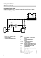
Heating system designs System version 1 System with Therm−Control Vitoplex 100, type SX1, up to 460 kW, Vitoplex 200, type SX2, up to 560 kW and Vitoplex 300, type TX3 C A1 20 C 21 5 143 146 A B A Boiler with Vitotronic 100 B DHW cylinder C Heating circuit with mixer 8 Plug § Boiler water temperature sensor % Cylinder temperature sensor aJ A Temperature sensor Therm Control sÖ A1 Mixers closed with external heating circuit control units sA Cylinder primary pump (accessories) fÖ Mains electrical
Heating system designs System version 1 (cont.) Required coding 02 : 2 Modulating burner operation*1 03 : 1 Oil fired operation (irreversible)*1 0d : 1 Therm−Control controls the mixers of downstream heating circuits 5862 730 GB Automatic changeover 00 : 2 With DHW cylinder 4A: 1 Connecting the Therm Control temperature sensor to plug aJA *1If required.
Heating system designs System version 1 (cont.) Possible applications Heating systems with distributor installed close to the boiler. The boiler water volume flow must be able to be reduced. If the factory−set temperatures are not reached at the Therm Control temperature sensor, Therm Control will activate the heating circuit control unit(s) or the heating circuit pump(s). In the start−up phase (e.g.
Heating system designs System version 2 Raising the return temperature with a shunt pump Vitogas 100 Vitomax 100, Vitomax 200 and Vitomax 300 Vitoplex 100, type SX1, Vitoplex 200, type SX2, and Vitoplex 300, type TX3 Vitorond 200 17B 17A 3 T1 143 146 40 41 90 21 5 C T2 29 A1 20 C A B A Boiler with Vitotronic 100 B DHW cylinder C Heating circuit with mixer Plug § % aJ A aJ B sÖ A1 5862 730 GB sA Boiler water temp. sensor Cylinder temp.
Heating system designs System version 2 (cont.) Required coding 02 : 2 Modulating burner operation*1 03 : 1 Oil fired operation (irreversible)*1 0d : 1 The temperature sensor on plug aJA controls the mixers of downstream heating circuits 00 : 2 With DHW cylinder 4A: 1 Connecting temperature sensor T1 to plug aJA 4b : 1 Connecting temperature sensor T2 to plug aJB *1If 12 required.
Heating system designs System version 2 (cont.) Temperature sensor T1 Wiring in heating systems with heating circuit control units which are not connected to the boiler control unit via the LON BUS. Required coding: "4C : 2". Possible applications Heating systems with distributor installed close to the boiler. The boiler water volume flow must be able to be reduced. Temperature sensor T2 activates the shunt pump, if the actual temperature falls below the required minimum return temperature.
Heating system designs System version 3 Raising the return temperature with shunt pump and three−way mixer Vitogas 100 Vitomax 100, Vitomax 200 and Vitomax 300 Vitoplex 100, type SX1, Vitoplex 200, type SX2, and Vitoplex 300, type TX3 Vitorond 200 C A1 52 29 T2 17B 17A 3 T1 143 146 40 41 90 21 5 C A B A Boiler with Vitotronic 100 B DHW cylinder C Heating circuit with mixer % aJ A aJ B sA sL *1For Boiler water temperature sensor Cylinder temperature sensor (accessories) Temperature sensor T1*1 T
Heating system designs System version 3 (cont.) Required coding 02 : 2 Modulating burner operation*1 03 : 1 Oil fired operation (irreversible)*1 0C : 1 Constant return temperature control Automatic changeover 00 : 2 With DHW cylinder 4A: 1 Connecting temperature sensor T1 to plug aJA 4b : 1 Connecting temperature sensor T2 to plug aJB 5862 730 GB Possible applications Heating systems where downstream heating circuits cannot be controlled, e.g. older heating systems or nurseries.
Heating system designs System version 4 System with Therm−Control Vitoplex 100, type SX1, to 460 kW, Vitoplex 200, type SX2, to 560 kW, and Vitoplex 300, type TX3 40 41 90 52 A1 143 146 A Boiler with Vitotronic 100 B DHW cylinder C Heating circuit with mixer A A Plug § Boiler water temperature sensor aJ A Temperature sensor Therm Control sÖ A1 Mixers closed with external heating circuit control units fÖ Mains electrical connection, 230V~/50 Hz fA Burner stage 1 gS A1 Motorised butterfly valve lÖ Bur
Heating system designs System version 4 (cont.) Codes must be set on every Vitotronic 100. Required coding 01 : 2 01 : 3 Multi−boiler system with cascade control via LON BUS Multi−boiler system with external cascade control via switching contacts 02 : 2 Modulating burner operation*1 03 : 1 Oil fired operation (irreversible)*1 Automatic changeover 5862 730 GB 4A: 1 *1If Connecting the Therm Control temperature sensor to plug aJA required.
Heating system designs System version 4 (cont.) Possible applications Heating systems with distributor installed close to the boiler. The boiler water volume flow will be reduced by the motorised butterfly valve. In multi−boiler system without Vitotronic 333, cascade and cylinder control must be provided by a higher control unit. If the factory−set temperatures are not reached at the Therm Control temperature sensor, Therm Control will regulate the motorised butterfly valves.
Heating system designs System version 5 Raising the return temperature for each boiler with a shunt pump Vitogas 100 Vitomax 100, Vitomax 200 and Vitomax 300 Vitoplex 100, type SX1, Vitoplex 200, type SX2, and Vitoplex 300, type TX3 Vitorond 200 C A1 20 A1 20 C 3 17B 17A T2 40 41 90 29 52 A1 143 146 T2 40 41 90 29 52 A1 143 146 3 17B 17A T1 T1 A B A A Boiler with Vitotronic 100 B DHW cylinder C Heating circuit with mixer Plug § 5862 730 GB aJ A aJ B sÖ A1 sL Boiler water temperature sen
Heating system designs System version 5 (cont.) Codes must be set on every Vitotronic 100. Required coding 01 : 2 01 : 3 Multi−boiler system with cascade control via LON BUS Multi−boiler system with external cascade control via switching contacts 02 : 2 Modulating burner operation*1 03 : 1 Oil fired operation (irreversible)*1 4A: 1 Connecting temperature sensor T1 to plug aJA 4b : 1 Connecting temperature sensor T2 to plug aJB *1If 20 required.
Heating system designs System version 5 (cont.) Possible applications Heating systems with distributor installed close to the boiler. The boiler water volume flow will be reduced by the motorised butterfly valve. In multi−boiler system without Vitotronic 333, cascade and cylinder control must be provided by a higher control unit. Temperature sensor T2 activates the shunt pump, if the actual temperature falls below the required minimum return temperature.
Heating system designs System version 6 Raising the return temperature with a common shunt pump Vitomax 100, Vitomax 200 and Vitomax 300 Vitoplex 100, type SX1, Vitoplex 200, type SX2, and Vitoplex 300, type TX3 C C 20A1 29 A Boiler with Vitotronic 100 B DHW cylinder C Heating circuit with mixer A 52 A1 143 146 T1 A Plug § Boiler water temperature sensor aJ A Temperature sensor T1 aJ B Temperature sensor T2 sÖ A1 Mixers closed with external heating circuit control units sL Shunt pump fÖ Mains el
Heating system designs System version 6 (cont.) Codes must be set on every Vitotronic 100.
Heating system designs System version 6 (cont.) Possible applications Heating systems with distributor installed close to the boiler. The boiler water volume flow must be able to be reduced via the heating circuits. In multi−boiler system without Vitotronic 333, cascade and cylinder control must be provided by a higher control unit. Temperature sensor T2 activates the shunt pump, if the actual temperature falls below the required minimum return temperature.
Heating system designs System version 7 Distribution pump and low pressure distributor Vitogas 100 Vitomax 100, Vitomax 200 and Vitomax 300 Vitoplex 100, type SX1, Vitoplex 200, type SX2, and Vitoplex 300, type TX3 Vitorond 200 C B A Boiler with Vitotronic 100 B DHW cylinder C Heating circuit with mixer 5862 730 GB 40 41 90 A T1 52 A1 143 146 3 17A T1 52 A1 143 146 40 41 90 3 17A C A Plug § Boiler water temperature sensor aJ A Temperature sensor T1 sÖ A1 Mixers closed with external heating
Heating system designs System version 7 (cont.) Codes must be set on every Vitotronic 100. Required coding 01 : 2 01 : 3 Multi−boiler system with cascade control via LON BUS Multi−boiler system with external cascade control via switching contacts 02 : 2 Modulating burner operation*1 03 : 1 Oil fired operation (irreversible)*1 0d : 1 Temperature sensor T1 controls the mixers of downstream heating circuits Automatic changeover *1If 26 Connecting temperature sensor T1 to plug aJA required.
Heating system designs System version 7 (cont.) Possible applications If the distributor is located in remote sub−stations (> 20 m). The heat transfer to the heating circuits must be able to be reduced. In multi−boiler system without Vitotronic 333, cascade and cylinder control must be provided by a higher control unit. The distribution pump will be regulated by the higher control unit. It must be started when a boiler is enabled.
Heating system designs System version 8 Distribution pump and injection control Vitogas 100 Vitomax 100, Vitomax 200 and Vitomax 300 Vitoplex 100, type SX1, Vitoplex 200, type SX2, and Vitoplex 300, type TX3 Vitorond 200 C A Boiler with Vitotronic 100 B DHW cylinder C Heating circuit with mixer 52 A1 143 146 40 41 90 A T1 A Plug § aJ A sÖ A1 Boiler water tempe.
Heating system designs System version 8 (cont.) Codes must be set on every Vitotronic 100.
Heating system designs System version 8 (cont.) Possible applications If the distributor is located in remote sub−stations (>20 m), and the heating circuits require heat immediately after a demand is present, e.g. blown air heaters. The heat transfer to the heating circuits must be able to be reduced. The cascade and cylinder control must be provided by a higher control unit. The distribution pump will be regulated by the higher control unit. It must be started when a boiler is enabled.
Heating system designs System version 9 Raising the return temperature with a three−way mixing valve Vitogas 100 Vitomax 100, Vitomax 200 and Vitomax 300 Vitoplex 100, type SX1, Vitoplex 200, type SX2, and Vitoplex 300, type TX3 Vitorond 200 C 3 17A 5862 730 GB A Boiler with Vitotronic 100 B DHW cylinder C Heating circuit with mixer 40 41 90 29 52 A1 143 146 40 41 90 29 52 A1 143 146 3 17A B C T1 T1 A A Plug § Boiler water temperature sensor aJ A Temperature sensor T1 sL Boiler circuit pump
Heating system designs System version 9 (cont.) Codes must be set on every Vitotronic 100.
Heating system designs System version 10 Raising the return temperature with a low loss header and a three−way mixing valve Vitogas 100 Vitomax 100, Vitomax 200 and Vitomax 300 Vitoplex 100, type SX1, Vitoplex 200, type SX2, and Vitoplex 300, type TX3 Vitorond 200 C C D 3 17A B 5862 730 GB A Boiler with Vitotronic 100 B DHW cylinder C Heating circuit with mixer D Low loss header 40 41 90 29 52 A1 143 146 40 41 90 29 52 A1 143 146 3 17A T1 T1 A A Plug § Boiler water temperature sensor aJ A T
Heating system designs System version 10 (cont.) Codes must be set on every Vitotronic 100.
Heating system designs System version 11 System with Vitocrossal 300 C 21 5 C 143 146 40 41 90 3 B A Plug § Boiler water temperature sensor % Cylinder temperature sensor (accessories) sA Cylinder primary pump (accessories) fÖ Mains electrical connection, 230V~/50 Hz fA Burner stage 1 lÖ Burner stage 2/mod.
Heating system designs System version 11 (cont.) Required coding 02 : 2 Modulating burner operation*1 0d : 0 Without Therm−Control Automatic changeover 00 : 2 With DHW cylinder *1If 36 required. 5862 730 GB Vitocrossal 300 is operated via the boiler control unit two−stage or modulating burners are regulated.
Heating system designs System version 12 Several heating circuits and one low temperature heating circuit Vitocrossal 300 E F C 21 5 G 143 146 or 3 40 41 90 B D A Plug § Boiler water temperature sensor % Cylinder temperature sensor (accessories) sA Cylinder primary pump (accessories) fÖ Mains electrical connection, 230V~/50 Hz fA Burner stage 1 lÖ Burner stage 2/mod.
Heating system designs System version 12 (cont.) Required coding 02 : 2 Modulating burner operation*1 0d : 0 Without Therm−Control Automatic changeover 00 : 2 With DHW cylinder Possible applications For heating circuits with varying temperatures. Vitocrossal 300 is operated via the boiler control unit two−stage or modulating burners are regulated. *1If 38 required. 5862 730 GB Vitocrossal 300 is equipped with two return connectors.
Heating system designs System version 13 Several heating circuits and one low temperature heating circuit Vitocrossal 300 C B D A D A Plug § Boiler water temperature sensor fÖ Mains electrical connection, 230V~/50 Hz fA Burner stage 1 gS A1 Motorised butterfly valve lÖ Burner stage 2/mod.
Heating system designs System version 13 (cont.) Codes must be set on every Vitotronic 100. Required coding 01 : 2 01 : 3 Multi−boiler system with cascade control via LON BUS Multi−boiler system with external cascade control via switching contacts 02 : 2 Modulating burner operation*1 0d : 0 Without Therm−Control Possible applications If the distributor is located in remote sub−stations (> 20 m). The heat transfer to the heating circuits must be able to be reduced.
Heating system designs System version 14 Several heating circuits and one low temperature heating circuit Vitocrossal 300 Vitoplex 100, type SX1, Vitoplex 200, type SX2, Vitoplex 300, type TX3 C 40 41 90 143 146 40 41 90 D A Plug § Boiler water temperature sensor aJ A Temperature sensor Therm Control fÖ Mains electrical connection, 230V~/50 Hz fA Burner stage 1 gS A1 Motorised butterfly valve lÖ Burner stage 2/mod.
Heating system designs System version 14 (cont.) Codes must be set on every Vitotronic 100.
Heating system designs System version 14 (cont.) Possible applications The cascade and cylinder control must be provided by a higher control unit. The Therm Control temperature sensor of the low temperature boiler controls the motorised butterfly valve and must reduce the boiler water volume flow of the low temperature boiler during the start−up phase (e.g. during commissioning or after night or weekend shutdown).
Heating system designs System version 15 Several heating circuits, one low temperature heating circuit and low temperature boiler with shunt pump Vitocrossal 300 Vitogas 100 Vitomax 100 Vitoplex 100, type SX1, Vitoplex 200, type SX2, and Vitoplex 300, type TX3 Vitorond 100 C 3 17B 17A T2 143 146 40 41 90 29 52 A1 143 146 3 40 41 90 C T1 D A Boiler with Vitotronic 100 B DHW cylinder C Heating circuit with mixer D Neutralising system 44 A A Plug § Boiler water temperature sensor aJ A Temperature
Heating system designs System version 15 (cont.) Codes must be set on every Vitotronic 100.
Heating system designs System version 15 (cont.) Possible applications The cascade and cylinder control must be provided by a higher control unit. The return temperature raising facility is available as an accessory or must be provided on site. Raise the return temperature through a shunt−pump and by closing the butterfly valve. Temperature sensor T1 controls the butterfly valve. Temperature sensor T2 switches the shunt pump.
Heating system designs System version 16 Several heating circuits, one low temperature heating circuit plus Vitoplex with Therm−Control and boiler circuit pump Vitocrossal 300 Vitoplex 100 (90 to 500 kW), Vitoplex 200 and Vitoplex 300, type TX3 (80 to 1750 kW) C A Boiler with Vitotronic 100 B DHW cylinder C Heating circuit with mixer D Neutralising system 5862 730 GB 40 41 90 143 146 40 41 90 D A 29 143 146 3 17A 3 B C A Plug § Boiler water temperature sensor aJ A Therm−Control temperature
Heating system designs System version 16 (cont.) Codes must be set on every Vitotronic 100.
Heating system designs System version 16 (cont.) Possible applications For heating circuits with temperature differentials y 20 K. The cascade and cylinder control must be provided by a higher control unit. The Therm−Control temperature sensor of the low temperature boiler regulates the boiler circuit pump. The boiler circuit pump is switched OFF when the Therm−Control temperature defaulted by the boiler coding card is not achieved.
Heating system designs System version 17 Three−way mixing valve, several heating circuits and one low temperature heating circuit Vitocrossal 300 Vitomax 100, Vitomax 200 and Vitomax 300 Vitoplex 100, type SX1, Vitoplex 200, type SX2, and Vitoplex 300, type TX3 C 3 17A 143 146 40 41 90 29 52 A1 143 146 3 40 41 90 C T1 D A Boiler with Vitotronic 100 B DHW cylinder C Heating circuit with mixer D Neutralising system 50 A A Plug § Boiler water temperature sensor aJ A Temperature sensor T1 sL Boil
Heating system designs System version 17 (cont.) Codes must be set on every Vitotronic 100.
Heating system designs System version 17 (cont.) Possible applications For heating circuits with temperature differentials y 20 K. The cascade and cylinder control must be provided by a higher control unit. Temperature sensor T1 records the return temperature. The boiler control unit regulates the three−way mixing valve to ensure that the system never falls below the minimum return temperature.
System extension DHW heating with a cylinder storage system Only in conjunction with single boiler systems 28 5 21 17B 52 20 A1 A1 C B 5862 730 GB A Boiler with Vitotronic 300 B Vitocell−L 300 C Vitotrans 222 A Plug % Terminals 1 and 2: Cylinder temperature sensor 1 (top) Terminals 2 and 3: Cylinder temperature sensor 2 (bottom) aJB Temperature sensor Vitotrans 222 sÖ A1 Primary pump sA Secondary pump sK DHW circulation pump gS A1 Motor for three−way mixing valve Possible applications In systems wit
System extension DHW heating with a cylinder storage system (cont.) Required coding 4C : 1 Primary pump connection on plug sÖ A1 4E : 1 Motor connection for three−way mixing valve on plug gS A1 55 : 3 Cylinder thermostat cylinder storage system Automatic changeover 4b : 1 Connection of temperature sensor Vitotrans 222 on plug aJB In conjunction with system version 2. The sensor input aJB is used to control Vitotrans 222. Therefore, the shunt pump must be controlled by a separate thermostat.
System extension System with flue gas/water heat exchanger With shunt pump G G E E D F D F C H A C B A B With boiler circuit pump G L D K G L D K 5862 730 GB C H A B C A B 55
System extension System with flue gas/water heat exchanger (cont.) A B Boiler with Vitotronic 100 Vitotrans 333 (flue gas/water heat exchanger) C Circulation pump Vitotrans 333 D Motorised butterfly valve Vitotrans 333 E Motorised boiler butterfly valve F Shunt pump G Low temperature heating circuit H DHW cylinder K Boiler circuit pump L Three−way mixing valve M Contactor relay, part no.
Installation Summary of electrical connections 145 151 90 41 21 52 20 29 50 40 156 156 A1/M1 A1/M1 150 5862 730 GB 17 B 17 A 5 3/2 15 143 146 57
Installation Main PCB low voltage § Boiler water temperature sensor % Cylinder temperature sensor Cylinder temperature sensor 2 for cylinder storage system (accessories) aG Flue gas temperature sensor (accessories) aJA Temperature sensor of Therm−Control or Return temperature sensor T1 (accessories) aJB Return temperature sensor T2 (accessories) or cylinder storage system temperature sensor aVD External hook−up aVG KM BUS user, e.g.
Installation Inserting cables and applying strain relief Installing the control unit on the boiler Route cables from below through the front panel of the boiler into the wiring chamber of the control unit. Installing the control unit on the boiler side Route cables from below, out of the cable channel into the control unit. A Cables with moulded strain relief B On−site cables Strip a maximum of 100 mm off the cable insulation.
Installation Inserting the boiler coding card Boiler Coding card Part no.
Installation Changing the high limit safety cut−out setting (if required) The high limit safety cut−out is supplied with a factory setting of 120 ºC. ! Please note If the high limit safety cut−out is to remain set to 120 ºC, also install a minimum pressure limiter (see page 84 and 136), to prevent injury and material losses. Note Vitocrossal 300 and Vitogas 100 must be changed over to 110 ºC.
Installation Changing the high limit safety cut−out setting (cont.) Conversion to 110 or 100 ºC (make T&G) 3. 1. 2. 5862 730 GB 4.
Installation Changing the high limit safety cut−out setting (cont.) Change to 110 or 100 ºC make EGO A 1. 2. A Slotted screw 2. Turn the slotted screw until the slot points to 110 or 100 ºC (once adjusted, the high limit safety cut−out cannot be reset). 5862 730 GB 1. Release the safety assembly and pivot it up.
Installation Changing the high limit safety cut−out setting (cont.) Conversion to 110 or 100 ºC, make JUMO 3. 1. 2. 5. 4. 1. Release the safety assembly. 4. Remove the high limit safety cut−out. 2. Remove reset button cover "E". 5. Turn the screw until the indicator points to 110 or 100 ºC. 5862 730 GB 3. Release the nut.
Installation Changing the control thermostat setting (if required) Conversion to 100 or 110 ºC In the delivered condition, the control thermostat is set to 95 ºC. AB 2. 3. 1. 1. Lever out and remove rotary selector "R". 2. Using a pair of pointed pliers, break off the cams from the stop dial which are identified in the illustration. A 75 to 100 ºC A, B 75 to 110 ºC 5862 730 GB Note Observe the setting of coding address "06". selected range. Turn rotary selector "R" clockwise to the end stop.
Installation Sensor connection 17B 17A 5 3 15 1 2 3 1 2 3 1 2 3 1 2 3 1 2 3 5862 730 GB A Temperature sensor T2 or Temperature sensor cylinder storage system B Therm−Control temperature sensor or temperature sensor T1 C Cylinder temperature sensor (accessories) D Cylinder temperature sensor 2 in conjunction with a cylinder storage system (accessories) E Boiler water temperature sensor F Flue gas temperature sensor (accessories) 66
Installation Pump connection Available pump connections sÖ Cylinder primary pump or Circulation pump flue gas/water heat exchanger sA Cylinder primary pump sL Shunt pump or boiler circuit pump Pumps 230 V~ L N PE N L External ON/OFF L N PE Pumps 400 V~ N L L1 L2 L3 N PE 5862 730 GB A B A Contactor B Pump C Mains supply in accordance with manufacturer’s instructions Rated current: 4 (2) A~ Recommended connecting cable: H05VV F3G 0.75 mm2 or H05RN F3G 0.
Installation Connecting an actuator with three−point output Use as: H Butterfly valve H Mixer motor H Three−way mixing valve M 1~ 52 A1 Rated voltage: 230 V~ Rated current: max. 0.2 (0.1) A Recommended connecting cable: H05VV−F4G 0.75 mm2 or H05RN−F4G 0.
Installation External hook−up in single boiler systems Operation with a two−stage burner Zero volt contacts of the higher control unit: Burner stage 1 ON Burner stage 2 ON The connections on plug aVD and aVH are required when connecting an external hook−up. The cylinder thermostat is activated when the cylinder temperature sensor (accessories) is connected.
Installation External hook−up in single boiler systems (cont.) Starting burner stage 1 Starting burner stage 1 and 2 Contact closed: Burner stage 1 is started. Burner stage 2 will only be started for maintaining the minimum temperature. The boiler water temperature is limited by the electronic maximum temperature limiter, if it is set below that of mechanical control thermostat "R". Contact closed: Both burner stages are switched ON.
Installation External hook−up in single boiler systems (cont.) Low temperature boiler operation with a modulating burner Connection modulating burner: H Burner stage 1 fA of Vitotronic 100 H Plug−in connector lÖ from Vitotronic 100 via the modulation controller (on site) to burner plug−in connector lÖ. H Adjust the minimum temperatures at the higher control unit with the modulation controller 5 K higher than the lower boiler water temperature.
Installation External hook−up in single boiler systems (cont.) Control unit settings Starting burner stage 1 Code "01: 1" (delivered condition) Code "02: 1" (delivered condition) Contact closed: Burner stage 1 is started. To maintain the minimum temperature, the burner is switched to full load via Vitotronic 100. An external modulation controller regulates the load−dependent modulation.
Installation External hook−up in single boiler systems (cont.
Installation External hook−up in single boiler systems (cont.) Control unit settings Starting burner stage 1 Code "01: 1" (delivered condition) Contact closed: Burner stage 1 is started. An external modulation controller regulates the load−dependent modulation. The boiler water temperature is limited by the electronic maximum temperature limiter, if it is set below that of mechanical control thermostat "R". The boiler water temperature must be set to the lower value.
Installation External hook−up in multi−boiler systems without LON Operation with a two−stage burner Zero volt contacts of the higher control unit: Burner stage 1 ON Burner stage 2 ON Enable boiler, open or close the butterfly valve 143 The connections on plug aVD and aVH are required when connecting an external hook−up. The DHW cylinder temperature and the load−dependent cascade control must be regulated by an external control unit.
Installation External hook−up in multi−boiler systems without LON (cont.) Starting burner stage 1 and 2 Enable boiler, butterfly valve Contact closed: Both burner stages are switched ON. The boiler water temperature is limited by the electronic maximum temperature limiter, if it is set below that of mechanical control thermostat "R". Burner stage 2 is shut down 2 K sooner. Contact closed: H Vitocrossal 300: The butterfly valve opens.
Installation External hook−up in multi−boiler systems without LON (cont.) Low temperature boiler operation with a modulating burner Connection modulating burner: H Burner stage 1 fA of Vitotronic 100 H Plug−in connector lÖ from Vitotronic 100 via the modulation controller (on site) to burner plug−in connector lÖ. H Adjust the minimum temperatures at the higher control unit with the modulation controller 5 K higher than the lower boiler water temperature.
Installation External hook−up in multi−boiler systems without LON (cont.
Installation External hook−up in multi−boiler systems without LON (cont.) Adjustments on every control unit Starting burner stage 1 Set code "01: 3" code "02: 1" (delivered condition) The high limit safety cut−out settings and other settings are subject to the system equipment and the safety equipment in accordance with DIN 4751 2. Contact closed: Burner stage 1 is started. Full load is switched ON only for maintaining the minimum temperature.
Installation External hook−up in multi−boiler systems without LON (cont.) Vitocrossal 300 operation with a modulating burner Connection modulating burner: H Burner stage 1 fA of Vitotronic 100 H Plug−in connector lÖ of Vitotronic 100 remains unused H Burner stage 2 lÖ modulating under the control of the on−site modulation controller H Burner stage 1 is enabled by the modulation controller via external demand aVH.
Installation External hook−up in multi−boiler systems without LON (cont.
Installation External hook−up in multi−boiler systems without LON (cont.) Adjustments on every control unit Starting burner stage 1 Set code "01: 3". Contact closed: Burner stage 1 is started. The boiler water temperature is limited by the electronic maximum temperature limiter, if it is set below that of mechanical control thermostat "R". The high limit safety cut−out settings and other settings are subject to the system equipment and the safety equipment in accordance with DIN 4751 2.
Installation External hook−up in multi−boiler systems with LON Zero volt contacts of the higher control unit: Boiler blocking Start boiler as last one in boiler sequence External changeover of stepped/ modulating burners 143 146 Boiler blocking Contact closed: The boiler is blocked. It is taken out of the boiler sequence, i.e. the butterfly valve or the three−way mixing valve for constant return temperature control is closed; shunt or boiler circuit pumps are switched OFF.
Installation External connections on plug aBÖ ! Please note ’Live’ contacts lead to short circuits or phase failure. The external connections must be zero volt. Plug aBÖ must remain plugged in, even if no connection is made. The plug−in adaptor for external safety equipment can be used for connecting several pieces of safety equipment (see page 136). C ON ON A B D E F External safety equipment H Remove jumper "STB" "STB". H Connect electrical safety equipment in series.
Installation External connections on plug aBÖ (cont.) ! Please note Connecting an external control unit can damage the boiler. Connect only safety shutdown equipment, e.g. temperature limiter, to these terminals. 3 2 1 ON ON When the heating system is shut down, the heating system is not protected against frost, and the boiler is not held at the lower boiler water temperature. M B A A Jumper "TR" "ON/TR" B Motorised flue gas damper Motorised flue gas damper H Remove jumper "TR" "ON/TR".
Installation Plugging in the LON communication module (if required) 5862 730 GB Plug in the LON communication module in accordance with the illustration in the control unit.
Installation Making the LON connection The Viessmann LON system is designed for "Line" BUS topology, i.e. with terminators at both ends. Connection with Viessmann LON cable A A C A 7m 7m B B C A Control unit or Vitocom B LON cable C Terminator Connection with H Viessmann LON cable and H Viessmann LON coupling A C A A 7m 7m 7m 7m 7m 7m B B B B B B D D D D C 5862 730 GB A Control unit or Vitocom B LON cable (max.
Installation Making the LON connection (cont.) Connection with H Viessmann LON cable, H on−site cable and H Viessmann socket for extensions up to 900 m long A C 7m A E E B F 7m 7m B B A E 7m C B max. 900 m A Control unit or Vitocom B LON cable, part no. 7143 495 C Terminator (standard delivery for Vitotronic 333) D Up to 99 users and the corresponding number of junction boxes and cables E Viessmann junction boxes, part no.
Installation Connecting an AC burner Pressure−jet oil/gas burners Connect the burner in accordance with the DIN 4791 or local regulations. The burner cables are included in the standard boiler delivery. Max. power consumption 6 (3) A.
Installation Connecting an AC burner (cont.
Installation Connecting an AC burner (cont.) Atmospheric burner The burner cables are included in the standard boiler delivery. Max. power consumption 6 (3) A.
Installation Connecting a three−phase burner zero volt safety chain ! Please note A jumper in the burner may possibly have to be removed from the external conductor to the control voltage. Observe the details of the burner supplier.
Installation Connecting a three−phase burner safety chain not zero volt ! Please note A jumper in the burner may possibly have to be removed from the external conductor to the control voltage. Observe the details of the burner supplier.
Installation Power supply Regulations Carry out the power supply connection and all earthing measures (e.g. fault current circuit) in accordance with IEC 364, the requirements of your local electricity supplier, VDE regulations or local regulations. Protect the power supply cable to the control unit with an appropriate fuse.
Installation Installing the control unit front 1. 6. 2. 5. 3. X20 X10 5862 730 GB 4. 7.
Installation Opening the control unit 2. 1. 5862 730 GB 3.
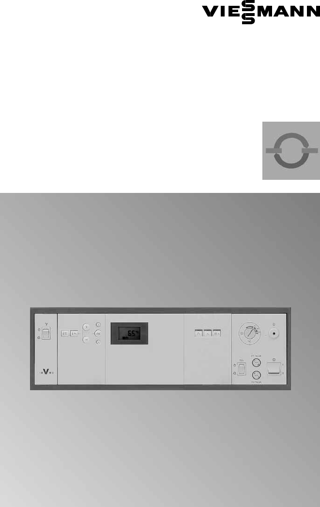
Commissioning Controls and display elements A B C D F1 6.3A (slow) F2 6.
Commissioning Checking the high limit safety cut−out Hold down the "TÜV" test key during this test (position "h"). There must be a minimum flow. The minimum circulation volume should be 10 % of the circulation volume at rated output. Reduce the heat consumption as far as possible. Control thermostat "R" is now bypassed. The burner remains switched ON until the boiler water temperature has reached the safety temperature and the high limit safety cut−out has switched OFF.
Commissioning Integrating the control unit into the LON system (cont.) Updating the LON user list. Only possible if all users are connected and the control unit is programmed as fault manager (code "79 : 1"). 1. Press L and d simultaneously for approx. 2 s. User check initiated (see page 100). 2. Press e. The user list is updated after approx. 2 min. User check completed.
Commissioning Carrying out a user check (in conjunction with the LON system) Communication with the system devices connected to the fault manager is tested with a user check. Preconditions: H The control unit must be programmed as fault manager (code "79 : 1"). H The LON user number must be programmed in all control units (see page 98). H The fault manager user list must be up to date (see page 98). 1. Press L and d simultaneously for approx. 2 s. User check initiated, all 7 arrows are displayed.
Commissioning Matching the coding addresses to the system version In code 2, set the following coding addresses: Code 2 see page 141. "00" System design "01" Single or multi−boiler system "02" Burner type "03" Oil or gas operation "07" Boiler number (only for multi−boiler systems) "0C" Return temperature raising "0d" Therm Control regulates ...
Commissioning Matching the coding addresses to the system version (cont.) Matching the control unit to a two−stage burner 1. Start up the burner. 2. Set the emissions test switch to "h" (see page 127). 3. Determine the maximum burner output through the fuel consumption. Record the relevant value. 4. Set the emissions test switch to "a". 5. Press K and d simultaneously for approx. 2 s. Relay test is activated. 6. Activate the "Burner stage 1 ON" function with a (display: 1). 7.
Commissioning Matching the coding addresses to the system version (cont.) Matching the control unit to a modulating burner Note The burner must be fully adjusted. To achieve a wide modulating range, set the minimum output as low as possible (take the chimney and flue gas system into account). 1. Start up the burner. 2. Set the emissions test switch to "h" (see page 127). 3. Wait, until the burner actuator is set to maximum output. 4. Determine the maximum burner output through the fuel consumption.
Commissioning Matching the coding addresses to the system version (cont.) Address Setting of 08 Units and tens of the determined maximum output; e.g. max. output: 225 kW select: 25 Values up to and including 199 kW can be entered directly. 09 Hundreds of the determined maximum output; e.g. max. output: 225 kW here: 2 15 Determined run time in seconds 0A Relationship between base output and max. output in percent; e.g. Base output: 72 kW Max.
Commissioning Checking outputs (actuators) and sensors (cont.) The following relay outputs can be controlled subject to system design: Display Relay function indication 11 12 13 14 15 16 17 18 19 10 11 Burner or stage1 ON Burner stage 1 and 2 ON or modulation open Burner modulation neutral Burner stage 1 ON (modulation closed) Output 20 ON Output 29 ON Output 52 open Output 52 neutral Output 52 closed Cylinder primary pump ON Central fault message ON Checking sensors 1. Press c.
Service scans Service level summary Function Entry User check in conjunction with a LON system Press L and d Press L and d simultaneously for approx. simultaneously for 2 s approx. 1 s Exit Page 100 Relay test Press K and d Press d simultaneously for approx. 2 s 104 Temperatures, boiler coding card and brief scans Press K and G Press d simultaneously for approx. 2 s 107 Operating conditions Press c Press c 109 Maintenance display Press d 111 Calling up Press d for approx.
Service scans Temperatures, boiler coding card and brief scans 1. Press K and G simultaneously for approx. 2 s. Entering the diagnostics level. 3. Press d. Leaving the diagnostics level. 2. Select the required scan with a or b.
Service scans Temperatures, boiler coding card and brief scans (cont.) Brief scans F8 8 8 8 8 8 Software version Communic− ations coprocessor SNVT configuration 0 = Auto 1 = Tool 0 N/A LON user number 1 2 N/A Subnet address/system no.
Service scans Scanning operating conditions 1. Press c. Scanning operating conditions is active. 3. Press c. Scanning operating conditions is completed. 2. Select the required operating condition scan with a or b. The following operating conditions can be scanned subject to the actual equipment level: Display indication Description Notes 0 0 1 LON user no.
Service scans Scanning operating conditions (cont.) Display indication P P 0 0 9 5 7 2 P P P Description Hours run, burner (stage 2) , ( g ) Notes The hours run can be reset to "0" with e e. Hours run are only approximate values Burner starts The burner starts can be reset to "0" with e Consumption Display only, if "26" or "29" has been set via coding address (only for two−stage operation).
Service scans Scanning and resetting maintenance displays After limits set up via coding addresses "1F", "21" and "23" (see page 144) have been reached, the programming unit display flashes one of the following messages, and the red fault indicator flashes. Note Set code "24:1" and then code "24:0", if maintenance is implemented before "Service" is displayed; the set maintenance parameters for hours run and intervals are reset to 0. 1. Scan maintenance messages with a or b.
Troubleshooting Faults which are displayed at the programming unit The red fault indicator flashes for every fault. A fault code flashes in the display if a fault message has been issued (see page 113). 1 Fault number 38 Fault code U Fault symbol Call up further fault codes with a or b. A fault can be acknowledged with d. The fault message in the display will be hidden, but the red fault indicator continues to flash. A central fault messaging facility connected to plug gÖ will be switched OFF.
Troubleshooting Faults which are displayed at the programming unit (cont.) Fault code System characteristics Cause Remedy 0f Control mode Maintenance "0F" is only displayed in fault history. Carry out maintenance Note Set code "24:0" after maintenance.
Troubleshooting Faults which are displayed at the programming unit (cont.) Fault code System characteristics Cause Remedy 58 Cylinder primary pump ON: Set cylinder water temperature = set boiler water temperature, priority control is cancelled or With cylinder storage system: Cylinder heating is started and stopped by cylinder temp. sensor 2 Lead broken Cylinder temp. sensor 1 Check cylinder temp.
Troubleshooting Faults which are displayed at the programming unit (cont.
Troubleshooting Fault code System characteristics Cause Remedy aa Control mode Therm Control configuration error Plug aJA of Therm Control temperature sensor not inserted Insert plug aJA Code "0d : 0" must be set for Vitocrossal ab Controlled operation, perhaps DHW cylinder cold Cylinder storage system configuration error: Code "55 : 3" has been set, but plug aJB is not plugged in and/or Code "4C : 1" and "4E : 1" have not been set Insert plug aJB and check code ac Control mode Return tempera
Troubleshooting Faults which are displayed at the programming unit (cont.) Fault code System characteristics Cause Remedy b1 Control mode Communication error Programming unit Check connections and replace programming unit if necessary (see page 128) b4 Emissions test mode Internal electronics fault bC5 bC6 Control mode Check electronics PCB.
Troubleshooting Faults which are displayed at the programming unit (cont.) System characteristics Cause Remedy c4 Control mode Communication with function extension 0−10 V faulty Check connections and cables/leads; if required replace function extension (see page 133).
Troubleshooting Faults which are displayed at the programming unit (cont.) Fault code System characteristics Cause Remedy ce Control mode Communication fault plug−in adaptor for external safety equipment Check plug−in adaptor for external safety equipment (see page 135) and connecting cable. Without plug−in adaptor, set code "94 : 0" Fault LON communication module Replace communication module (see page 128).
Troubleshooting Faults which are displayed at the programming unit (cont.) LON users fault messages Only if the control unit is the fault manager (code "79:1"). Fault code System characteristics Cause Remedy 01 Control mode A user fault has occurred, e.g.
Troubleshooting Faults which are displayed at the programming unit (cont.) Fault code System characteristics Cause Remedy 99 Control mode Fault message active at Vitocom 300 Check external connections at Vitocom 300 No connection to Vitocom 300 Check coding (see page 99) Check connecting LON cable Update user list (see page 99) Carry out a user check (see page 100) Downloading fault codes from the fault memory (fault history) The most recent 10 faults are saved and may be called up.
Function description Boiler water temperature control Brief description Coding addresses which influence the boiler water temperature control 02 to 06, 08 to 0A, 13 to 1C For a description, see page 140. 5862 730 GB The boiler water temperature is regulated by controlling the two−stage or modulating burner.
Function description Boiler water temperature control (cont.
Function description Cylinder temperature control (only for single boiler systems) Brief description The cylinder thermostat operates with a constant temperature. It is the result of starting and stopping the cylinder primary pump. The switching differential is ±2.5 K. Coding addresses which influence the cylinder thermostat 4E, 54, 55, 56, 58 to 5A, 60 to 63, 67 to 69. For a description, see page 147.
Function description Cylinder temperature control (only for single boiler systems) (cont.) Control sequence H The cylinder primary pump runs on after cylinder heating, until the difference between the boiler water and the DHW temperature is less than 7 K or the weather−compensated set flow temperature has been reached or the actual temperature is 5 K higher than the set DHW temperature or the maximum run−on time (adjustable via coding address "62") has been reached.
Function description Cylinder temperature control (only for single boiler systems) (cont.) Code "55:2": Cylinder temperature control with 2 cylinder temperature sensors Cylinder temperature sensor 1 enables the cylinder primary pump, and is evaluated for stop conditions during the pump run−on time.
Components Components from the parts list For parts list, see page 153. Main PCB 230 V~ Electronics PCB The main PCB comprises: H Relays and outputs for controlling pumps, actuators and the burner H Slot for power supply unit and boiler control unit Microprocessor with software When replacing the PCB: 1. Record the codes and adjustments made at the control unit. 2. Replace the PCB.
Components Components from the parts list (cont.) Programming unit LON communication module (accessories) Setting the: H Heating program H Set values H Coding Displaying: H Temperatures H Operating conditions H Faults Fuses F1: 6.3 A (slow), 250 V, max. power loss x 2.5 W, to protect the actuators, pumps, and all electronics F2: 6.3 A (slow), 250 V, max. power loss x 2.5 W, to protect the burner Burner connecting cables For boilers with H Pressure−jet oil/gas burners, connection see page 89.
Components Components from the parts list (cont.) TEST key For testing the high limit safety cut−out. For a description, see page 98. Control thermostat H Type TR 55.18029.020, make EGO, DIN TR 110302 or EM 1 TK/b1 60002846, make JUMO, DIN TR 77703 or Type 751.X32X6.
Components Components from the parts list (cont.) Boiler water temperature sensor and cylinder temperature sensor Connection See page 66. Checking sensor 1. Pull plug § or %. 760 740 720 2. Check the sensor resistance at terminals "1" and "2" or "2" and "3" (if a second cylinder temperature sensor has been connected) of the plug. 700 680 660 640 Resistance in 620 600 580 560 540 Specification Protection: IP 32 Permiss.
Components Components from the parts list (cont.) Contact temperature sensor and immersion temperature sensor For recording the return temperature. Connection See page 66. Checking sensor 1. Pull plug aJ. 740 720 700 680 660 640 600 580 560 540 20 30 40 50 60 70 80 90 100 Return temperature in ºC 3. Compare the test result with the actual temperature (for scanning, see page 107). Check the installation and replace sensor, if necessary, in case of severe deviation. Specification Protection: IP 32 Permiss.
Components Flue gas temperature sensor, part no. 7450 630 The sensor records the flue gas temperature and monitors the set limit. Connection See page 66. Checking the flue gas temperature sensor 1. Pull plug aG. 1020 2. Check the sensor resistance at terminals "1" and "2" of the plug. 980 3. Compare the test result with the actual temperature (for scanning, see page 107). Check the installation and replace sensor, if necessary, in case of severe deviation.
Components Boiler coding card To match the control unit function to the boiler (see page 60). Function extension 0−10 V, part no. 7174 718 24V 5V To default an additional set system temperature via a 0−10 V input for a range from 10 to 100 ºC or 30 to 120 ºC. For signalling reduced mode.
Components Function extension 0−10 V (cont.
Components Plug−in adaptor for external safety equipment, part no. 7143 526 For the connection of external safety equipment to DIN 4751−2 H Low water indicator H Maximum pressure limiter H Minimum pressure limiter H Additional high limit safety cut−out In addition for the connection of H Controlled external burner shutdown H Three external fault messages. Upper part of the plug−in adaptor B B B Zero volt contact on plug a−D.
Components Plug−in adaptor for external safety equipment (cont.) Lower part of the plug−in adaptor B B C B C B C X8 150 150 150 ON ON ON ON TR ON TR ON TR ON TR ON TR TR TR TR N N N N X7 D X2 D X3 D 6 5 4 3 2 1 X6 6 5 4 3 2 1 X4 G 150 X1 E X5 A F 136 H Remove the corresponding jumper when connecting the external safety equipment. H When connecting a motorised flue gas damper, plug aBÖ of the flue gas damper is inserted into socket "X1" of the plug−in adaptor.
Components Vitoair draught stabiliser, part no. 7338 725 and 7339 703 A To the burner B To the control unit Function check Press the motor rotary selector and turn it to its central position. H Enable burner from control unit → The rotary selector should move towards "3". Colour coding to DIN IEC 60 757 BK black GN/YE green/yellow H Burner OFF → The rotary selector should move towards "5".
Components Motorised flue gas damper, part no. 9586 973 and 9586 974 When connecting, remove jumper "TR" "ON/TR". 150 STB ON ON N STB TR TR A 1 2 3 F M ~ C B You can check the switch function by measuring its voltage: Flue gas damper closed (switch open) no voltage at terminal 3. Flue gas damper open (switch closed) voltage at terminal 3.
Coding Resetting codes to the delivered condition 1. Press L and G simultaneously for approx. 2 s, until the first two arrows appear in the display. 2. Press e. Code 1 Calling up code 1 1. Press K and L simultaneously for approx. 2 s, until the first arrow appears in the display. Access to coding level 1. 3. Change the value with a or b; confirm with d. The value is saved and does not flash for approx. 2 s. Then the display flashes again. Further addresses can now be selected with a or b. 2.
Coding Code 1 (cont.) Coding in the delivered condition Boiler/burner 02 : 1 Two−stage g burner Possible change 02 : 0 02 : 2 03 : 1 03 : 0 Gas fired operation 03 : 2 Burner (mod.
Coding Code 2 Calling up code 2 1. Press L and G simultaneously for approx. 2 s, until the first two arrows appear in the display; confirm with d. Access to coding level 2. 3. Change the value with a or b; confirm with d. The value is saved and does not flash for approx. 2 s. Then the display flashes again. Further addresses can now be selected with a or b. 2. Select the required coding address with a or b, the address flashes; confirm with d, the value flashes. 4.
Coding Code 2 (cont.) Coding in the delivered condition Possible change Boiler/burner (cont.) 04 : *1 Switching g hysteresis y (Note see page 151) 04 : 0 04 : 1 04 : 2 Switching hysteresis 4 K Heat demand−dependent switching hysteresis: ERB50 function (values from 6 to 12 K) ERB80 function (values from 6 to 20 K) Burner (mod.
Coding Code 2 (cont.) Coding in the delivered condition Possible change Burner (two−stage/mod.) (see page 102) (cont.
Coding Code 2 (cont.) Coding in the delivered condition Possible change Boiler/burner (mod.) (see page 103) 15 : 10 Actuator operating time 10 s 15 : 5 to 15 : 199 Operating time adjustable from 5 to 199 s; for Vitocrossal 300, type CV3, with MatriX burner set "15 : 19" Burner (two−stage/mod.
Coding Code 2 (cont.) Coding in the delivered condition Possible change Boiler/burner 23 : 0 No time interval for burner maintenance 23 : 1 to 23 : 24 Adjustable time interval from 1 to 24 months 24 : 1 Maintenance indication in display (address is automatically set and must be manually reset after maintenance) 26 : 1 to 26 : 99 27 : 1 to 27 : 199 Input of 0.1 to 9.9; 1 step ¢ 0.
Coding Code 2 (cont.) Possible change Coding in the delivered condition Boiler 2d : 0 Shunt pump control function only ON if boiler is enabled 2d : 1 Shunt pump control function ON, independent of whether boiler is enabled or not Operating time for butterfly valve actuator, three−way mixer or mixer motor in conjunction with return temperature control 125 s 40 : 5 to 40 : 199 Operating time adjustable from 5 to 199 s 4A : 0 Sensor aJA not installed 4A : 1 Sensor aJA installed (e.g.
Coding Code 2 (cont.) Coding in the delivered condition Possible change DHW 55 : 0 Cylinder heating, hysteresis ± 2.5 K 55 : 1 Adaptive cylinder heating active (speed of temp.
Coding Code 2 (cont.) Coding in the delivered condition Possible change DHW (cont.) 61 : 1 The cylinder primary pump starts immediately 61 : 0 The cylinder primary pump will be switched ON subject to the boiler water temperature 62 : 10 The cylinder primary pump will run on for a max.
Coding Code 2 (cont.) Coding in the delivered condition Possible change General 76 : 0 Without communication module 76 : 1 With LON communication module; will be recognised automatically 76 : 2 Do not adjust. 77 : 2 to 77 : 99 LON user number, adjustable from 1 to 99 Note Allocate each number only once.
Coding Code 2 (cont.) Coding in the delivered condition Possible change General (cont.) 98 : 1 9b : 0 9C: 20 9d : 0 98 : 1 to 98 : 5 System number adjustable from 1 to 5 External default of the set flow temperature via plug aVH 9b : 1 to 9b : 127 Set flow temperature in case of external demand via plug aVH adjustable from 1 to 127 ºC LON user monitoring When there is no response from a user, values defaulted by the control unit continue to be used for a further 20 min.
Coding Burner switching hysteresis Burner Switching hysteresis 4 K (04:0) ON Time OFF +2 set −2 low heat demand average heat demand high heat demand Heat−demand dependent switching hysteresis (only with outside temp. sensor) Burner ERB50 function (04:1) Subject to heat demand, values between 6 and 12 K result. ON Time OFF +9 +3 set −3 low heat demand average heat demand high heat demand Burner ERB80 function (04:2) Subject to heat demand, values between 6 and 20 K result.
5862 730 GB Coding 152
Parts list Parts list When ordering spare parts Quote the part no. and serial no. (see type plate A) as well as the item no. of the required parts (as per this parts list). Obtain standard parts from your local supplier.
Parts list Parts list (cont.
Parts list Parts list (cont.
Connection and wiring diagrams 5862 730 GB Summary 156
Connection and wiring diagrams Summary (cont.
Connection and wiring diagrams 5862 730 GB A10 A7 A2 A6 A9 A8 22.5V 5.
Connection and wiring diagrams Main PCB low voltage (cont.
Connection and wiring diagrams 5862 730 GB F1 6.3A (slow) 250V F2 6.
Connection and wiring diagrams Main PCB 230 V~ (cont.
Specification Specification Rated voltage: 230 V~ Rated frequency: 50 Hz Rated current: 2 (6) A ~ Power consumption: 5 W Safety class: I Protection level: IP 20 D to EN 60529, safeguard through appropriate design and installation Function: Type 1 B to EN 60730 1 Permissible ambient temperature H in operation: 0 to 40 ºC Use in living space and boiler rooms (standard ambient conditions) H during storage and transport: 20 to 65 ºC Rated capacity of relay outputs at 230 V~ for H Switching output or Primary
Keyword index Keyword index A AC burner connection, 89 Actuators, 68 Actuators, checking, 104 Adaptive cylinder heating, 125, 147 Additional function for DHW heating, 124, 147 Applicability, 168 B Boiler circuit pump, 67 Boiler coding card H Inserting and summary, 60 H Scanning, 107 Boiler water temperature, 107, 109 Boiler water temperature control, 122 H Component, 130 Boiler water temperature sensor H Installing, 66 Brief scans, 108 Burner, H Connecting, 89 H Connecting cables, 128 H Programming, 141 H
Keyword index Keyword index (cont.
Keyword index Keyword index (cont.
Keyword index Keyword index (cont.
5862 730 GB
Applicability Applicability Vitotronic 100, type GC1 Only for integration/installation on/in Viessmann boilers. Viessmann Werke GmbH & Co KG D 35107 Allendorf Tel: +49 6452 70 0 Fax: +49 6452 70 27 80 www.viessmann.de Viessmann Limited Hortonwood 30, Telford Shropshire, TF1 7YP, GB Tel: +44 1952 675000 Fax: +44 1952 675040 E−mail: info−uk@viessmann.com 168 5862 730 GB Subject to technical modifications. Printed on environmentally friendly, chlorine−free bleached paper For control unit Part no.