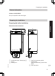
Installation and service instructions VIESMANN for contractors Vitodens 100-W Type WB1B, 9.0 to 35.0 kW Wall mounted gas fired condensing boiler Natural gas and LPG version Gas Council no. 41-819-12; 41-819-13; 41-819-14 (gas fired condensing boilers) 47-819-18; 47-819-19; 47-819-20 (gas fired condensing combi boilers) VITODENS 100-W 5366 836 GB 9/2008 Please keep safe.
Safety instructions Safety instructions Please follow these safety instructions closely to prevent accidents and material losses. Safety instructions explained Danger This symbol warns against the risk of injury. ! Please note This symbol warns against the risk of material losses and environmental pollution. Note Details identified by the word "Note" contain additional information.
Safety instructions Safety instructions (cont.) If you smell flue gas Danger Flue gas can lead to life-threatening poisoning. ■ Shut down the heating system. ■ Ventilate the boiler room. ■ Close all doors leading to the living space. Repair work ! Please note Repairing components which fulfil a safety function can compromise the safe operation of your heating system. Replace faulty components only with original Viessmann spare parts.
Index Index Installation instructions Preparing for installation Product information.............................................................................................. Preparing for installation....................................................................................... 5 5 Installation sequence Installing the boiler and making all connections................................................... 9 Opening the control unit................................................................
Preparing for installation Product information Vitodens 100-W, WB1B Set up for operation with natural gas.
Preparing for installation Preparing for installation (cont.
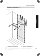
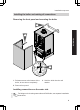
Preparing for installation Preparing for installation (cont.) Fitting the wall retainer 11 5 Installation Ø10 250 155 B 5366 836 GB A A Installation template Vitodens B Opening for the balanced flue 1. Position the supplied installation template on the wall. 2. Mark out the rawl plug holes.
Preparing for installation Preparing for installation (cont.) 3. Drill 710 mm holes and insert the supplied rawl plugs. 4. Fit wall retainer with screws supplied. Preparing the connections 2. Prepare gas connection. 3. Prepare the electrical connections. Observe valid IEEE standards. ■ A 1.5 m long power cable is fitted as standard. ■ Accessory cables: NYM-O 2-core min. 0.5 mm2. 5366 836 GB 1. Prepare the water connections. Flush the heating system.
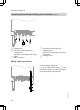
Installation sequence Installing the boiler and making all connections Removing the front panel and mounting the boiler 3. Installation 2. 1. 2x 1. Release screws at the bottom of the boiler; do not remove completely. 3. Hook the boiler into the wall retainer. 2. Remove front panel. 5366 836 GB Installing connections on the water side For fittings on the heating water side and DHW side, see separate installation instructions.
Installation sequence Installing the boiler and making all connections (cont.) B C D E z A z ¨ A Heating flow B Gas fired condensing boiler: Cylinder flow Gas fired condensing combi boiler: DHW C Gas connection D Gas fired condensing boiler: Cylinder return Gas fired condensing combi boiler: Cold water E Heating return Safety valve connection Connect safety valve drain A (7 15 mm) with visible outlet B to the dewatering system or route with visible outlet through the external wall.
Installation sequence Installing the boiler and making all connections (cont.) Gas connection 1. Connect gas shut-off valve to connection A. ! A Please note Excessive test pressure may damage the boiler and the gas valve. Max. test pressure 150 mbar. Where higher pressure is required for tightness tests, separate the boiler and the gas valves from the gas supply pipe (undo the fitting). 5366 836 GB 3. Vent the gas supply pipe. 11 Installation 2. Carry out a leak/tightness test.
Installation sequence Installing the boiler and making all connections (cont.) Condensate connection Connect condensate drain A with a slope and a pipe vent to the public sewer. Observe the local waste water regulations. Note Fill the siphon with water before startup. A Filling the siphon with water Fill a minimum of 0.3 l of water into the flue gas connection. Please note At commissioning, flue gas may be emitted from the condensate drain. Fill the siphon with water before start-up.
Installation sequence Installing the boiler and making all connections (cont.) Balanced flue connection Connect the balanced flue. During installation and positioning of the flue gas system, observe building regulations part L and BS 5440. Installation Flue gas system installation instructions. Opening the control unit 2. 2x 3. 1.
Installation sequence Opening the control unit (cont.) ! Please note Electronic modules can be damaged by electrostatic discharges. Touch earthed objects, such as heating or water pipes, to discharge static loads. Electrical connections Information regarding the connection of accessories For details of accessories, also observe their separate installation instructions provided.
Installation sequence Electrical connections (cont.) A B C D Note Gas fired condensing boiler without DHW cylinder: For operation without a DHW cylinder, set rotary selector "tw" to "0". Only for weather-compensated mode: Outside temperature sensor (accessory) Open Therm device Connection line (accessory) Jumper (remove when connecting a room thermostat) E Power supply (230 V, 50 Hz). Danger Incorrect core termination can cause severe injuries and damage to the equipment.
Installation sequence Electrical connections (cont.) Routing connecting cables and closing control unit ! Please note Power cables will be damaged if they contact hot parts. When routing and securing power cables on site, ensure that the maximum permissible temperatures for these cables are not exceeded. 3. 2. 5366 836 GB 1.
Commissioning, inspection, maintenance Steps - commissioning, inspection and maintenance For further information regarding the individual steps, see the page indicated Commissioning steps Inspection steps Maintenance steps • • • • • • • 1. Filling the heating system.............................................. 18 2. Venting the boiler by flushing out (after venting system)............................................................................ 20 3.
Commissioning, inspection, maintenance Further details regarding the individual steps Filling the heating system ! Please note Unsuitable fill water increases the level of deposits and corrosion and may lead to boiler damage. ■ Thoroughly flush the entire heating system prior to filling it with water. ■ Only use fill water of potable quality. ■ Soften fill water harder than 300 ppm. ■ An antifreeze additive suitable for heating systems can be mixed with the fill water. 1. Close the gas shut-off valve. 2.
Commissioning, inspection, maintenance Further details regarding the individual steps (cont.) B A 4. Open shut-off valves A and (if installed) B. 5. Fill the heating system via an external filling facility. (Minimum system pressure > 0.8 bar). Note The external filling facility must meet the requirements of the Water Fittings Regulations 1999 Section G 24.1 and G 24.2.
Commissioning, inspection, maintenance Further details regarding the individual steps (cont.) Venting the boiler by flushing out (after venting system) 1. Connect the drain hose on shut-off valve A to a drain. A 2. Close shut-off valve B. 3. Open valves A and C and flush at mains pressure, until no sound of escaping air can be heard. 4. First shut off valve A then valve C. 5. Operating pressure ≥ 0.8 bar; adjust with valve C. 6. Open shut-off valve B.
Commissioning, inspection, maintenance Further details regarding the individual steps (cont.) 2. Simultaneously turn rotary selectors "tw" and "tr" to their central position. "SERV" appears on the display. r 3. Within 2 s turn rotary selector "rt" to the top right area. "r" and the set value flash on the display. r 5. Do not adjust the rotary selectors for 15 s. The set operating mode is then saved and the control unit returns to standard mode.
Commissioning, inspection, maintenance Further details regarding the individual steps (cont.) Checking the CO2 or O2 content Vitodens 100-W is factory-set for natural gas. During commissioning or maintanance, the CO2 and CO have to be measured at the boiler flue adaptor testpoint to check the flue integrity. Subject to the Wobbe index, the CO2 content fluctuates between 7.4 % and 10.5 %. And CO of up to 500 ppm is acceptable.
Commissioning, inspection, maintenance Further details regarding the individual steps (cont.) 4. Adjust the upper output: Turn rotary selector "tr" to the control range on the right. The display shows 5 bars for upper output. 5. Measure the CO2 content for upper output. The CO2 content must be between 7.4 and 10.5 %. 6. Adjust the lower output: Turn rotary selector "tr" to the left control range. The display shows 1 bar for lower output. 7. Test the CO2 content for lower output.
Commissioning, inspection, maintenance Further details regarding the individual steps (cont.) Burner removal F 4x C B E D A 1. Switch OFF the power. 5. Release gas supply pipe E fitting. 2. Shut off the gas supply. 6. Undo four screws F and remove the burner. 3. Pull power cables from fan motor A, gas valve B and electrodes E. Please note To prevent damage, never rest the burner on the gauze assembly. 5366 836 GB 4. Pull the venturi extension D from the fan.
Commissioning, inspection, maintenance Further details regarding the individual steps (cont.) Checking the burner gasket and the burner gauze assembly Check burner gasket A for damage and replace if required. Replace the burner gauze assembly if it is damaged. E D C A 4x Service B 1. Remove electrode B. 5366 836 GB 2. Undo the three cheese-head screws and remove thermal insulating ring C. 3. Undo four Torx screws and remove burner gauze assembly D with its gasket E. 4.
Commissioning, inspection, maintenance Further details regarding the individual steps (cont.) 5. Refit thermal insulation ring C. Fixing screw torque: 3.5 Nm. 6. Refit the electrode B. Fixing screw torque: 3.5 Nm. Checking and adjusting electrodes 1. Check the electrode for wear and contamination. 2. Clean the electrode with a small brush (not with a wire brush) or emery paper. 8+2 3. Check the electrode gaps.
Commissioning, inspection, maintenance Further details regarding the individual steps (cont.) 1. Use a vacuum cleaner to remove residues from the heat exchanger A inside the combustion chamber. 2. If required, spray slightly acidic, chloride-free cleaning agents based on phosphoric acid onto heat exchanger A and let the solution soak in for approx. 20 min. 3. Thoroughly flush the heat exchanger A with water.
Commissioning, inspection, maintenance Further details regarding the individual steps (cont.) Checking the condensate drain and cleaning the siphon 1. Check that the condensate can drain freely at the siphon. 2. Remove all hoses from siphon A. 3. Release locking tabs at opening B from underneath and remove siphon A upwards. 4. Clean siphon A and reinstall. 5. Refit all hoses. Secure drain hose with cable ties. A 5366 836 GB B 6. Fill siphon A with water. by pouring about 0.
Commissioning, inspection, maintenance Further details regarding the individual steps (cont.) Burner installation A 4x 5366 836 GB D 1. Install the burner and torque screws A diagonally with 4.0 Nm. 5. Reopen gas supply and switch on power supply. 2. Insert new gasket and tighten the fittings on gas supply pipe B 6. Check the gas connections for tightness. 3. Plug the venturi extension C into the fan. Danger Escaping gas leads to a risk of explosion. Check all fittings for gas-tightness. 4.
Commissioning, inspection, maintenance Further details regarding the individual steps (cont.) Check gas equipment for tightness at operating pressure Danger Escaping gas leads to a risk of explosion. Check gas equipment for tightness. Fitting the front panel 1. 2. 2x 2. Tighten screws at the bottom. 5366 836 GB 1. Push front panel into place on the guide rails.
Commissioning, inspection, maintenance Further details regarding the individual steps (cont.) Instructing the system user 5366 836 GB Service The system installer must hand the operating instructions to the system user and instruct him/her in the operation of the system.
Troubleshooting Function sequence and possible faults Display screen no Measures Increase set value and ensure heat is drawn off no after approx. 51 s fault F9 Check the fan, fan connecting cables, power at the fan and fan control no Fault F4 Check the connection ignition module no Fault F4 Check the gas train (control voltage 230 V); check the gas supply pressure no Fault F4 Check the ionisation current, check the electrode adjustment and the gas pipe for airlocks.
Troubleshooting Function sequence and possible faults (cont.
Troubleshooting Fault messages on the display (cont.) Fault code System characteris- Cause Measures on the dis- tics play 51 No DHW heating Outlet temperature Check the sensor (see sensor shorted out page 43). 52 Burner blocked Short circuit, flow sensor Check connections and lead; replace sensor if required. Check the sensor (see page 40). 58 No DHW heating 59 No DHW heating Cylinder temperature sensor lead broken Outlet temperature Check the sensor (see sensor lead broken page 43).
Troubleshooting Fault messages on the display (cont.) 5366 836 GB F3 Burner in a fault state Flame signal is already present at burner start F4 Burner in a fault state No flame signal is present F8 Burner in a fault state The fuel valve closes too late F9 Burner in a fault state Fan speed too low during the burner start FA Burner in a fault state Fan not at standstill FC Burner blocked Electrical fan control (control unit) faulty Measures Check the heating system fill level.
Troubleshooting Fault messages on the display (cont.) Fault code System characteris- Cause on the dis- tics play Fd Burner blocked Burner control unit fault FF Burner blocked Burner control unit fault Measures Check ignition electrodes and connecting cables. Check whether a strong interference (EMC) field exists near the equipment. Press "Reset" (see page 36). Replace control unit if the fault persists. Check ignition electrodes and connecting cables.
Troubleshooting Repairs Removing front panel 2. 1. 2x 2. Remove front panel. Service 1. Release screws at the bottom of the boiler; do not remove completely. Outside temperature sensor 5366 836 GB 1. Open the control unit casing. See page 13.
Troubleshooting Repairs (cont.) 2. Disconnect cables from outside temperature sensor. X21 X7 X20 4 3 2 1 20 3. Check the sensor resistance and compare it with the curve. 4. Replace the sensor in case of severe deviation.
Troubleshooting Repairs (cont.) Boiler water temperature sensor 1. Pull the leads from boiler water temperature sensor A and check the resistance.
Troubleshooting Repairs (cont.) Resistance in kΩ 20 2. Check the sensor resistance and compare it with the curve. 10 8 6 4 3. In case of severe deviation, drain boiler on the heating water side and replace the sensor. 2 1 0.8 0.6 0.4 10 30 50 70 90 110 Temperature in °C Danger The boiler water temperature sensor is immersed in the heating water (risk of scalding). Drain the boiler before replacing the sensor.
Troubleshooting Repairs (cont.) Resistance in kΩ 20 10 8 6 4 2. Compare the sensor resistance with the curve. 3. Replace the sensor in case of severe deviation. 2 1 0.8 0.6 0.4 10 30 50 70 90 110 Temperature in °C Checking the temperature limiter 5366 836 GB Service If the burner control unit cannot be reset after a fault shutdown, although the boiler water temperature is below approx. 95 °C, check the temperature limiter.
Troubleshooting Repairs (cont.) 1. Pull the leads from temperature limiter A. A 2. Check the continuity of the temperature limiter with a multimeter. 3. Remove the faulty temperature limiter. 4. Install a new temperature limiter. 5366 836 GB 5. Press "Reset" at the control unit (see page 36).
Troubleshooting Repairs (cont.) Checking the outlet temperature sensor (gas fired condensing combi boiler) 1. Pull the leads from outlet temperature sensor A 2. Check the sensor resistance and compare it with the curve. A 2 1 0.8 0.6 0.4 10 30 50 70 90 110 Temperature in °C Note Water can leak when replacing the outlet temperature sensor. Shut off the cold water supply. Drain the DHW line and the plate-type heat exchanger (DHW side). 43 Service 10 8 6 4 3.
Troubleshooting Repairs (cont.) Checking the flue gas temperature sensor 1. Pull the leads from flue gas temperature sensor A. 2. Check the sensor resistance and compare it with the curve.
Troubleshooting Repairs (cont.) Resistance in kΩ 20 3. Replace the sensor in case of severe deviation. 10 8 6 4 2 1 0.8 0.6 0.4 10 30 50 70 90 110 Temperature in °C Replacing flow limiter (gas fired condensing combi boiler) A 1. Drain the boiler from the DHW side. 2. Pivot the control unit downwards. B 3. Undo screws A. C 4. Remove the cap B. 6. Select new flow limiter C corresponding to boiler serial no. (see type plate) and the following table. 7. Insert new flow limiter C. 5366 836 GB 8.
Troubleshooting Repairs (cont.) Serial number (Type plate) 7373 061 7373 063 7373 065 Flow rate l/min Colour 10 12 14 black red brown Checking or replacing the plate-type heat exchanger (gas fired condensing combi boiler) D D E F H G A B E Heating water flow F Heating water return G Cold water H DHW 1. Shut off and drain the boiler on the heating water and the DHW side. 2. Flip down control unit.
Troubleshooting Repairs (cont.) 3. Push the three-way valve drive A slightly upwards. 4. Turn the three-way valve B with drive A 1/8 anticlockwise and remove. 5. Remove two screws C from the plate-type heat exchanger and remove plate-type heat exchanger D with gaskets. Note During removal, small amounts of water may trickle out and escape from the removed plate-type heat exchanger. 6. Check the DHW side for scaling and, if required, clean or replace the platetype heat exchanger. 7.
Troubleshooting Repairs (cont.) 5366 836 GB 3. Check fuse F4.
Gas type conversion Converting from LPG to natural gas Removing gas restrictor 3x C B Service F E D 5366 836 GB A 1. Pull power cable from gas train A. 3. Undo three screws C and remove gas train A. 2. Remove union nut B.
Gas type conversion Converting from LPG to natural gas (cont.) 4. Remove gas restrictor D from gas train. 6. Remove or void gas type sticker on the top of the boiler (next to the type plate). 5. Fit gas train A with new gaskets E and F. Fixing screw torque C: 3 Nm. Union nut torque B: 22 Nm. Converting gas type on the control unit 1. Turn ON/OFF switch ON. 2. Simultaneously turn rotary selectors "tw" and "tr" to their central position. "SERV" appears on the display. r 3.
Gas type conversion Converting from LPG to natural gas (cont.) 4. Adjust the control unit to natural gas or LPG by turning the rotary selector "tw". The display shows: ■ "0" for operation with natural gas or ■ "1" for operation with LPG. 5. Do not adjust the rotary selectors for 15 s. The set operating mode is then saved and the control unit returns to standard mode. Checking the CO2 content 5366 836 GB Service See page 22.
Control unit Functions and operating conditions in weather-compensated mode In weather-compensated mode, the boiler water temperature is regulated subject to the outside temperature.
Designs E D 5366 836 GB M L K Service H G A F B C Connection and wiring diagram A B Stepper motor diverter valve Ignition/Ionisation C Vitotrol 100, type UTA or on-site room temperature controller 53
Designs Connection and wiring diagram (cont.) D E F G H § $ Boiler water temperature sensor Outlet temperature sensor (gas fired condensing combi boiler) Cylinder temperature sensor % (gas fired condensing boiler) Flue gas temperature sensor aG Circulation pump 230V~ sÖ Gas solenoid valve dG Temperature limiter fJ a-Ö Fan motor 230V~ a-ÖA Fan control aVL Flow sensor 5366 836 GB K L M X ...
Parts lists Parts lists 001 002 003 004 005 006 007 009 010 011 012 013 014 015 5366 836 GB 016 017 018 019 020 021 023 027 029 030 031 032 033 034 035 036 037 039 Heat exchanger Moulded hose heating water flow Moulded hose heating water return Hose connector adapter Heating water return connection elbow Heating water flow connection elbow Gas supply pipe Pressure gauge Boiler flue connection Drain valve Siphon Flue gas gasket Diaphragm expansion vessel Connection line; diaphragm expansion vessel Boile
Parts lists Parts lists (cont.
Parts lists Parts lists (cont.
Parts lists Parts lists (cont.
Parts lists Parts lists (cont.
Parts lists Parts lists (cont.
Specification Specification Rated voltage: Rated frequency: Rated current: Safety class: Protection: 230 V~ 50 Hz 2.0 A~ I IP X4 to EN 60529 Temperature limiter setting: Line fuse (mains): 100 °C (fixed) max. 16 A Permissible ambient temperature ■ during operation: 0 to +40 °C during storage and ■ transport: -20 to +65 °C Gas fired condensing boiler, class II 2H3P Rated output range in heating mode TV/TR 50/30 °C kW 9 to 26 kW 8.2 to 23.7 TV/TR 80/60 °C Rated output range for DHW heatkW ing 8.2 to 23.
Specification Specification (cont.) Gas fired condensing combi boiler, class II 2H3P Rated output range in heating mode TV/TR 50/30 °C kW 9 to 26 kW 8.2 to 23.7 TV/TR 80/60 °C Rated output range for DHW heatkW ing 8.2 to 26.0 Rated thermal load range 8.4 to 27.1 kW 11 to 26 11 to 26 10.0 to 10.0 to 23.7 23.7 10.0 to 10.0 to 35.0 30.0 10.3 to 10.3 to 36.5 31.3 * *2 m3/h kg/h W 2.9 2.1 111 3.3 2.4 144 3.9 2.9 167 bar 10 10 10 l/min 10.6 12.3 14.3 l/min 10.0 12.0 14.
Certificates Declaration of conformity Declaration of conformity for the Vitodens 100-W We, Viessmann Werke GmbH&Co KG, D-35107 Allendorf, confirm as sole responsible body that the product Vitodens 100-W complies with the following standards: DIN 4702-6 EN 483 EN 625 EN 677 EN 50 165 EN 55 014 EN 60 335 EN 61 000-3-2 EN 61 000-3-3 In accordance with the following Directives, this product is designated _-0085: 90/396/EEC 92/ 42/EEC 2004/108/EC 2006/95/EC This product complies with the requirements of th
Keyword index Keyword index C Cleaning the combustion chamber....26 Cleaning the heat exchanger.............26 Commissioning..................................18 Condensate connection.....................12 Condensate drain...............................28 Connection diagram...........................53 Connections.........................................9 Connections on the water side.............9 Cylinder temperature sensor .............40 D Declaration of conformity...................
5366 836 GB
5366 836 GB
5366 836 GB
Subject to technical modifications. chlorine-free bleached paper Printed on environmentally friendly, 68 Viessmann Limited Hortonwood 30, Telford Shropshire, TF1 7YP, GB Telephone: +44 1952 675000 Fax: +44 1952 675040 E-mail: info-uk@viessmann.com 5366 836 GB Viessmann Werke GmbH&Co KG D-35107 Allendorf Telephone: +49 6452 70-0 Fax: +49 6452 70-2780 www.viessmann.