CDE6520/CDE7520/CDE8620 CDE6520-W/CDE7520-W/ CDE8620-W Commercial Display User Guide IMPORTANT: Please read this User Guide to obtain important information on installing and using your product in a safe manner, as well as registering your product for future service. Warranty information contained in this User Guide will describe your limited coverage from ViewSonic Corporation, which is also found on our web site at http:// www.viewsonic.
Thank you for choosing ViewSonic As a world leading provider of visual solutions, ViewSonic is dedicated to exceeding the world’s expectations for technological evolution, innovation, and simplicity. At ViewSonic, we believe that our products have the potential to make a positive impact in the world, and we are confident that the ViewSonic product you have chosen will serve you well.
Compliance Information This section addresses all connected requirements and statements regarding regulations. Confirmed corresponding applications shall refer to nameplate labels and relevant markings on the unit. FCC Statement This device complies with Part 15 of the FCC Rules. Operation is subject to the following two conditions: (1) this device may not cause harmful interference, and (2) this device must accept any interference received, including interference that may cause undesired operation.
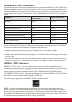
Declaration of RoHS Compliance This product has been designed and manufactured in compliance with Directive 2011/65/EU of the European Parliament and the Council on restriction of the use of certain hazardous substances in electrical and electronic equipment (RoHS2 Directive) and is deemed to comply with the maximum concentration values issued by the European Technical Adaptation Committee (TAC) as shown below: Substance Proposed Maximum Concentration Actual Concentration Lead (Pb) 0.1% < 0.
Safety Precautions FOR OPTIMUM PERFORMANCE, PLEASE NOTE THE FOLLOWING WHEN SETTING UP AND USING THE LCD COLOR MONITOR: • DO NOT REMOVE MONITOR BACK COVER. There are no user serviceable parts inside and opening or removing covers may expose you to dangerous shock hazards or other risks. Refer all servicing to qualified service personnel. • Do not spill any liquids into the cabinet or use your monitor near water.
CAUTION: Immediately unplug your monitor from the wall outlet and refer servicing to qualified service personnel under the following conditions: • When the power supply cord or plug is damaged. • If liquid has been spilled, or objects have fallen into the monitor. • If the monitor has been exposed to rain or water. • If the monitor has been dropped or the cabinet damaged. • If the monitor does not operate normally by following operating instructions.
Table Of Contents 1. Unpacking and Installation................... 1 1.1. Unpacking....................................... 1 1.2. Package Contents........................... 1 1.3. Installation Notes............................. 1 1.4. Mounting on a Wall.......................... 2 1.4.1. VESA Grid............................. 2 2. Parts and Functions.............................. 4 2.1. Control Panel.................................. 4 2.2. Input/Output Terminals.................... 5 2.3.
Copyright Information Copyright © ViewSonic® Corporation, 2020. All rights reserved. ViewSonic®, the three birds logo, OnView, ViewMatch, and ViewMeter are registered trademarks of ViewSonic® Corporation. Macintosh and Power Macintosh are registered trademarks of Apple Inc. Microsoft, Windows, and the Windows logo are registered trademarks of Microsoft Corporation in the United States and other countries. VESA is a registered trademark of the Video Electronics Standards Association.
1. Unpacking and Installation 1.1. Unpacking • • • • This product is packed in a carton, together with the standard accessories. Any other optional accessories will be packed separately. Due to the size and weight of this display it is recommended for two people to move it. After opening the carton, ensure that the contents are complete and in good condition. 1.2.
1.4. Mounting on a Wall To mount this display to a wall, you will have to obtain a standard wall-mounting kit (commercially available). We recommend using a mounting interface that complies with UL1678 standard in North America. Protective Sheet VESA Grid Table 1. Lay a protective sheet on a table, which was wrapped around the display when it was packaged, beneath the screen surface so as not to scratch the screen face. 2.
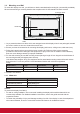
Ventilation Requirements for enclosure locating To allow heat to disperse, leave space between surrounding objects as shown in the diagram below. 100 mm 100 mm 100 mm 100 mm NOTES: When installing the display on a wall, proper installation. We accept no liability for installations not performed by a professional technician.
2. Parts and Functions 2.1. Control Panel 5 4 3 2 1 1 2 3 4 5 Press to On or Off the display. Press the MENU key to enter the main menu, and it confirms the operation in the SOURCE menu. Press the INPUT key to enter the input source menu, and to select the signal source. It is used to confirm the operation under the MENU operations. In the OSD menu, press the ◄/► key to adjust the value of the selected item. Press the ▲/▼ key to select an item in the OSD menu.
2.2. Input/Output Terminals 1 HDMI OUT SPDIF HDMI 1 (ARC) HDMI 2 2 DisplayPort RS232 VGA PC LINE IN USB 3.0 USB 1 AUDIO OUT LAN USB 2 3 4 5 6 7 8 9 10 11 12 13 1 MAIN POWER SWITCH Switch the main power on/off. 9 PC LINE IN Audio input from VGA source (3.5mm stereo phone). 2 AC IN AC power input from the wall outlet. 10 USB PORT 3.0/ 11 USB 2.0 PORT Connect your USB storage device 3 HDMI OUT HDMI video/audio output. 12 AUDIO OUT Audio output to external AV device.
2.3. Remote Control 1 2.3.1. General functions 2 3 1 4 2 4 5 3 6 [ASPECT] button Adjust aspect ratio for HDMI/DP/VGA 7 [VOL +/-] button Volume +/- 1 8 [SLEEP] button Backlight On/Off 10 10 12 15 16 17 18 [ Mute 13 14 [NUMERIC] buttons 6 9 8 9 11 [INPUT] button Input Source selection [P.MODE] button Image adjustment menu for HDMI/DP/VGA [S.
2.3.2. Inserting batteries in the remote control The remote control is powered by two 1.5V AAA batteries. To install or replace batteries: 1. Press and then slide the cover to open it. 2. Align the batteries according to the (+) and (–) indications inside the battery compartment. 3. Replace the cover. Caution: The incorrect use of batteries can result in leaks or bursting.
3. Connecting External Equipment 3.1. Connecting External Equipment (DVD/VCR/VCD) 3.1.1. Using DispalyPort video input DVD / VCR / VCD DP Out DisplayPort DVD / VCR / VCD HDMI 1 (ARC) [DP IN] HDMI 2 HDMI Out 3.1.2. Using HDMI video input [HDMI IN] DVD / VCR / VCD HDMI 1 (ARC) HDMI Out HDMI 2 [VGA AUDIO IN] PC LINE IN PC [HDMI IN] VGA IN 3.2. Audio Out [VGA IN] Connecting a PC VG A Out D-Sub 15 pin 3.2.1.
3.2.2. Using HDMI input PC HDMI 1 (ARC) HDMI 2 HDMI Out [HDMI IN] 3.2.3. Using VGA input PC HDMI 1 (ARC) HDMI 2 VGA PC LINE IN Audio In Audio Out AUDIO OUT [AUDIO OUT] DP Out HDMI Out [VGA Audio IN] [HDMI IN] Stereo Amplifier [VGA IN] 3.3. Connecting Audio Equipment 3.3.1.
4. Operation 4.1.4. System Mode Select system to select Normal mode, remove screen sharing Apps or disable Embedded OS. NOTE: The control button described in this section is mainly on the remote control unless specified otherwise. 4.1. Start-up and initial Setting 4.1.1. Welcome Select your language and tap “Next”. 4.2. Watch the Connected Video Source INPUT button. 1. Press 2. Press or button to select a device, then press OK button. 4.1.2.
5. Launcher 5.1. Setting 5.2.1. DHCP DHCP mode: (1) Cannot modify IP Address, Netmask, DNS Address and Gateway. (2) If connect successfully, it will display current network configuration. Press HOME button on remote control to show the Launcher screen. Main items: (1) Network (2) Device (3) System 5.2.2. Static IP In Static IP mode, user can input IP Address, Netmask, DNS address and Gateway. Note: IP address, netmask, DNS address and gateway address input limitation. (1)Format: I. number 0-9 II.
5.3. Device (4) Apps A. Display applications information. Divide into 4 groups: Signage Display/System Tools/Display/Apps 5.3.1. General Settings (1) Signage Display 1. Signage Display Name Set up Signage Dispay Name Note: Input limitation: (1) length: Max 36 characters (2) format: no limit (2) A. General settings B. Source settings C. Security System Tools (3) A. Clear Storage B. Reset C. Import&Export D. Clone Display A. Backlight 2.
After setup, it will show App name 5.3.2. Source Settings 1. Custom App User can set up the application for Customer Source. Note (1) Only display User Installed app. (2) Will not show up system pre-install app If set up customer APK, PD will open customer app when switch source to Customer mode. If no set up customer APK, PD will show Launcher screen when switch source to Customer mode. 5.3.3. Security 1. External Storage Enable: USB External Storage Lock. Disable: USB External Storage Unlock.
5.3.6.2 Import Signage Display Settings Impor vs_setting.db from viewsonic folder under USB. (1) Import vs_setting.db. Include OSD setting, Android settings but “Signage Display Name” and “Boot Logo” (2) Auto install 3rd par ty apk from viewsonic/ app. 5.3.5. Reset Factory Reset can recover to Factory default settings. Press OK to execute Reset function automatically. 5.3.6. Import & Export The function of Impor t & Export Signage Display settins. 5.3.7.
5.3.9. Backlight User can set the panel backlight. After select update.zip file, Signage Display will restart and start to update. 5.4. 5.4.2.2. Online System updates Online system update can select (1) Auto Update: When display power off, system will auto check the new version from OTA server. If new version found, system will auto update. After update complete, sytem will turn off. (2) Set Schedule: User can set the update time. (3) Manual update: User can update the OTA package manually.
6. OSD Menu 6.1. An overall view of the On-Screen Display (OSD) structure is shown below. You can use it as a reference for further adjusting your display. Settings 6.1.1. Picture menu Brightness Adjust the overall image and background screen brightness. Navigating the OSD menu using the remote control: 1. Press the MENU button to display the OSD menu. Contrast Adjust the image contrast ratio for the input signal. 2. Press [ ] [ ] [ ] or [ ] button to select its menu item or to adjust its value.
RGB Range Select the mode to display the HDMI or DVI signal according to their signal format depending on their source device. • • • Screen reset Reset all settings in the Screen menu to factory preset values. 6.1.3. Audio menu {Auto} - Auto detection signal format. {Full Range} - displaying the signal that uses all 256 levels (from level 0 to 255). {Limited Range} - displaying the signal that uses 16 to 235 levels of 256 levels for each R, G, and B. Flicker Free Turn on/off the Flicker function.
Audio reset Reset all settings in the Audio menu to factory preset values. • • 6.1.4. Time • • • Input: Platform will go to this select source automatically after the schedule on. Days of the week: Set Sunday, Monday,Tuesday, Wednesday, Thursday, Friday, Saturday. Every week: Set lifecycle. Back: Does not change schedule data. Save: Save schedule data. Slideshow interval Setting the photo slideshow interval for USB auto play.
Boot on Logo Choose to enable or disable the picture of Logo when turn on your display. The options are: 6.1.5. Advanced • • • 1. If Logo set to ON, ViewSonic logo and animation ViewSonic logo will show. 2. If Log set to OFF, neither ViewSonic logo nor animation logo will not show. 3. If Logo set to USER, custom logo option in settings is not set, then there will be no boot logo when power on. 4. If Logo set to USER, custom logo option in settings is set, there will be only custom logo when power up.
Switch on state Select the display status used for the next time you connect the power cord. • • • 6.1.6. About {Power off} - The display will remain off when the power cord is connected to a wall outlet. {Forced on} - The display will turn on when the power cord is connected to a wall outlet. {Last status} - The display will return to the previous power status WOL Choose to turn on or off the wake on LAN function.
7.
H.264 .mov H.265 MPEG-4 MJPEG H.264 .mp4 H.265 MPEG-4 Video .vob MPEG-2 H.264 .mpg/ .mpeg MPEG-1 MPEG-2 H.264 .ts H.265 MPEG-2 VC-1(AP) Audio .m4v MPEG-4 .aac GAAC .ape Monkey's Audio .flac FLAC .m4a ALAC .mp3 MPEG1/2 layer3 .ogg Vorbis .
8. Input mode Graphic Resolution: Standard Resolution Active Resolution H Pixels 640 720 800 832 1024 1152 V Lines 480 400 600 624 768 864 VGA/DVI Refresh Rate (V Frequency/Hz) H Frequency (KHz) Pixel Rate (MHz) Stand for Mode 59.941 31.469 25.175 VESA 72.810 37.861 31.500 VESA 75.000 37.500 31.500 VESA 70.080 31.467 28.320 IBM 85.038 37.927 35.500 VESA 56.250 35.156 36.000 VESA 60.317 37.879 40.000 VESA 72.188 48.077 50.000 VESA 75.000 46.875 49.
DVI 3840 2160 23.976 53.946 296.703 VESA 24.000 54.000 297.000 VESA 25.000 56.250 297.000 VESA 29.970 67.430 296.703 VESA 30.000 297.000 67.500 VESA HD Resolution: Standard Resolution Video 480i 576i 480p 576p HDMI/DP 720p 1080i 1080p Active Resolution Refresh Rate (V Frequency/ Hz) H Frequency (KHz) Pixel Rate (MHz) Stand for Mode 59.939 15.734 13.500 EIA-861D 60.000 15.750 13.513 EIA-861D H Pixels V Lines 720 480 1440 480 59.939 15.734 27.
HDMI/DP • • • • • • • • 4K 3840 2160 23.976 53.946 296.703 3840 2160 24.000 54.000 297.000 3840 2160 25.000 56.250 297.000 3840 2160 29.970 67.430 296.703 3840 2160 30.000 67.500 297.000 3840 2160 50.000 112.500 594.000 3840 2160 60.000 135.000 594.000 The PC text quality is optimum in HD 1080 mode (1920 x 1080, 60Hz). Your PC display screen might appear different depending on the manufacturer (and your par ticular version of Windows).
9. Cleaning and Troubleshooting 9.1. Cleaning When Using the Display • Do not bring your hands, face or objects close to the ventilation holes of the display. The top of the display is usually very hot due to the high temperature of exhaust air being released through the ventilation holes. Burns or personal injuries may occur if any body parts are brought too close. Placing any object near the top of the display could also result in heat related damage to the object as well as the display itself.
9.2. Troubleshooting Problems Possible causes Solutions The Power indicator does not A. the monitor is not powered on come on A. Check if the power cord is connected, and switch ON the monitor. The Power indicator is on, but A. The Video wire is detached or no image is displayed connected improperly B. No video signal input A. Connect or replace the video wire, and ensure proper and correct connection; B. Check the signal source, and check if it is properly connected at the output end.
10. Technical Specifications 10.1. CDE6520/CDE6520-W Display: Item Screen Size (Active Area) Aspect Ratio Number of Pixels Pixel Pitch Displayable Colors Brightness Contrast Ratio (Typical) Viewing Angle Specifications 165 cm / 65 inch 16:9 3840 (H) x 2160 (V) 0.372 (H) x 0.372 (V) [mm] 10bit, 1.07 Billion colors 450 cd/m² 1200:1 178 degrees In/Out Terminals: Item Specifications 16W (L) + 16W (R) [RMS]/8Ω Speaker Output Internal Speakers 1 Way 1 Speaker System 82 dB/W/M/160 Hz ~ 13 KHz Audio Output 3.
Environmental Condition: Item Operational Temperature Storage Operational Humidity Storage Operational Altitude Storage Internal Speaker: Item Type Input Impedance Output Sound Pressure Frequency Response Specifications 0 ~ 40°C -10 ~ 60°C 20 ~ 80% RH (No condensation) 10 ~ 80% RH (No condensation) 0 ~ 3,000 m 0 ~ 3,658 m Specifications 1 Way 1 Speaker 16 W (RMS) 8Ω 82 dB/W/M 160 Hz ~ 13 KHz 29
10.2. CDE7520/CDE7520-W Display: Item Screen Size (Active Area) Aspect Ratio Number of Pixels Pixel Pitch Displayable Colors Brightness Contrast Ratio (Typical) Viewing Angle Specifications 191 cm / 75 inch 16:9 3840 (H) x 2160 (V) 0.4296(H) × 0.4296 (W) [mm] 10bit, 1.07 Billion colors 450 cd/m² 1200:1 178 degrees In/Out Terminals: Item Specifications 16W (L) + 16W (R) [RMS]/8Ω Speaker Output Internal Speakers 1 Way 1 Speaker System 82 dB/W/M/160 Hz ~ 13 KHz Audio Output 3.5mm jack x 1 0.
Environmental Condition: Item Operational Temperature Storage Operational Humidity Storage Operational Altitude Storage Internal Speaker: Item Type Input Impedance Output Sound Pressure Frequency Response Specifications 0 ~ 40°C -10 ~ 60°C 20 ~ 80% RH (No condensation) 10 ~ 80% RH (No condensation) 0 ~ 3,000 m 0 ~ 3,658 m Specifications 1 Way 1 Speaker 16 W (RMS) 8Ω 82 dB/W/M 160 Hz ~ 13 KHz 31
10.3. CDE8620/CDE8620-W Display: Item Screen Size (Active Area) Aspect Ratio Number of Pixels Pixel Pitch Displayable Colors Brightness Contrast Ratio (Typical) Viewing Angle Specifications 218 cm / 86 inch 16:9 3840 (H) x 2160 (V) 0.4935(H) × 0.4935 (W) mm [mm] 10bit, 1.07 Billion colors 450 cd/m2 1200:1 178 degrees In/Out Terminals: Item Specifications 16W (L) + 16W (R) [RMS]/8Ω Speaker Output Internal Speakers 1 Way 1 Speaker System 82 dB/W/M/160 Hz ~ 13 KHz Audio Output 3.5mm jack x 1 0.
Environmental Condition: Item Operational Temperature Storage Operational Humidity Storage Operational Altitude Storage Internal Speaker: Item Type Input Impedance Output Sound Pressure Frequency Response Specifications 0 ~ 40°C -10 ~ 60°C 20 ~ 80% RH (No condensation) 10 ~ 80% RH (No condensation) 0 ~ 3,000 m 0 ~ 3,658 m Specifications 1 Way 1 Speaker 16 W (RMS) 8Ω 82 dB/W/M 160 Hz ~ 13 KHz 33
11. RS232 Protocol 11.1. Introduction This document describes the hardware interface spec and software protocols of RS232 interface communication between ViewSonic Commercial TV / Digital Signage and PC or other control unit with RS232 protocol. The protocol contains three sections command: • Set-Function • Get-Function • Remote control pass-through mode * In the document below, “PC” represents all the control units that can send or receive the RS232 protocol command. 11.2. Description 11.2.1.
11.3. Protocol 11.3.1. Set-Function Listing The PC can control the TV/DS for specific actions. The Set-Function command allows you to control the TV/ DS behavior in a remote site through the RS232 port. The Set-Function packet format consists of 9 bytes. Set-Function description: Length: Total Byte of Message excluding “CR”. TV/DS ID Identification for each of TV/DS (01~98; default is 01) If we want to set all TV/DS settings, use the TV/DS ID “99”, and it will not have Reply command on this function.
Example2: Set Brightness as 176 for TV-02 and this command is NOT valid Send (Hex Format) Command Name Length ID Command Value1 Value2 Value3 CR Type 0x30 0x38 0x73 0x24 0x31 0x37 0x36 0x0D Hex 0x32 Reply (Hex Format) Name Length ID Hex 0x34 0x30 0x32 Command Type CR 0x2D 0x0D Set function table: Basic function Set Function Length Power on*3.2.1 8 ID Command Type (ASCII) s Command Code Code (ASCII) ! (Hex) 21 /off(standby) Value Range (Three ASCII Comments bytes) 000: STBY 1.
Brightness 8 s $ 24 000 ~ 100 900:Bright down (-1) 901: Bright up (+1) *3.1.1 Backlight*3.2.0 8 A B 42 000 ~ 100 1. For Android platform whose main mode is controlled by backlight and the other sources are controlled by brightness. 2. Derived from Color calibration. *3.2.0 Power lock 8 s 4 34 000: Unlock Volume 8 s 5 35 001: Lock 000 ~ 100 *See note in details 900: Volume down(-1) Mute Button lock Menu lock Number *3.1.1 Key Pad *3.1.
Optional function Set Function Length Contrast Sharpness Color Tint Backlight On_Off*3.2.3 Color mode 8 8 8 8 8 8 ID Command Type (ASCII) s s s s s s Command Code Code (ASCII) # % & ‘ ( Value Range (Three ASCII (Hex) 23 25 26 27 28 bytes) 000 ~ 100 000 ~ 100 000 ~ 100 000 ~ 100 000: Off 29 001: On 000: Normal ) Comments 001: Warm 002: Cold Surround sound Bass Treble Balance Picture Size 8 8 8 8 8 s s s s s .
11.3.2. Get-Function Listing The PC can interrogate the TV/DS for specific information. The Get-Function packet format consists of 9 bytes which is similar to the Set-Function packet structure. Note that the “Value” byte is always = 000 Get-Function description: Length: Total Byte of Message excluding “CR”. TV/DS ID Identification for each of TV/DS (01~98; default is 01).
Reply (Hex Format) Name Length ID Hex 0x38 0x30 0x35 Command Command Type 0x72 0x62 Value1 Value2 Value3 CR 0x30 0x36 0x37 0x0D Example2: Get Brightness from TV-05, but the Brightness command ID is error and it is NOT in the command table.
Get function table: Basic function Get Function Length ID Command Command Type (ASCII) Code Code (Hex) 62 42 Get-Bright- 8 g (ASCII) b ness Get-Back- 8 a B light Response Comments Range (Three ASCII bytes) 000 ~ 100 000 ~ 100 *3.2.0 1. For Android platform whose main mode is controlled by backlight and the other sources are controlled by brightness. 2. Derived from Color calibration. *3.2.0 Get-Volume 8 g f 66 000 ~ 100 Get-Mute 8 g g 67 000: Off 6A 001: On (muted) 000~ 1.
Get-Thermal 8 g 0 30 000~100: 0~+100 deg C -01~-99: Get-Operation hour 8 g 1 31 -1~-99 deg C 000 *3.2.0 1. Accumulated hours in 6-digit integer (000,001~ 999,999)*3.2.0 2. Can not be reset when FW update and Factory initiation*3.2.2 3. Reply in new 32-byte Get-Device name Get-MAC ad- 8 8 g g 4 34 5 35 000 format*3.2.0 Reply in new 32-byte 000 format*3.2.0 (for the model with LAN) dress Reply in new 32-byte Get-IP ad- format*3.2.
Optional function Get Function Length ID Command Command Type (ASCII) Code Code (Hex) 61 Response Range Comments (Three ASCII Get-Contrast 8 g (ASCII) a Get-Sharp- 8 g c 63 000 ~ 100 ness Get-Color 8 g d 64 000 ~ 100 Get-Tint 8 g e 65 000 ~ 100 Get-Backlight 8 g h 68 000: Off 32 001: On Y00~Y00 Last 2 digits On_Off*3.2.
Key 1 2 3 4 5 6 7 8 9 0 RECALL (LAST) INFO (DISPLAY) ASPECT (ZOOM, SIZE) VOLUME UP (+) VOLUME DOWN (-) MUTE CHANNEL/PAGE UP (+)/ BRIGHTNESS+ CHANNEL/PAGE DOWN (-)/ BRIGHTNESSPOWER SOURCES (INPUTS) SLEEP MENU UP DOWN LEFT (-) RIGHT (+) OK (ENTER, SET) EXIT RED ■ (F1) GREEN ■ (F2) YELLOW ■ (F3) BLUE ■ (F4) NOTE: Code (HEX) 01 02 03 04 05 06 07 08 09 0A 0B 0C 0D 0E 0F 10 11 12 1. This IR-pass-through code is different from the RCU key code. 2.
12. Other Information Customer Support For technical support or product service, see the table below or contact your reseller. NOTE: You will need the product serial number. Country/ Region Website Country/ Region Website Asia Pacific & Africa Australia www.viewsonic.com/au/ Bangladesh www.viewsonic.com/bd/ 中国 (China) www.viewsonic.com.cn 香港 (繁體中文) www.viewsonic.com/hk/ Hong Kong (English) www.viewsonic.com/hk-en/ India www.viewsonic.com/in/ Indonesia www.viewsonic.com/id/ Israel www.
Limited Warranty ViewSonic® LCD Commercial Display What the warranty covers: ViewSonic warrants its products to be free from defects in material and workmanship, under normal use, during the warranty period. If a product proves to be defective in material or workmanship during the warranty period, ViewSonic will, at its sole option, repair or replace the product with a like product. Replacement product or parts may include remanufactured or refurbished parts or components.
Limitation of implied warranties: There are no warranties, express or implied, which extend beyond the description contained herein including the implied warranty of merchantability and fitness for a particular purpose. Exclusion of damages: ViewSonic’s liability is limited to the cost of repair or replacement of the product. ViewSonic shall not be liable for: 1.
Mexico Limited Warranty ViewSonic® LCD Commercial Display What the warranty covers: ViewSonic warrants its products to be free from defects in material and workmanship, under normal use, during the warranty period. If a product proves to be defective in material or workmanship during the warranty period, ViewSonic will, at its sole option, repair or replace the product with a like product. Replacement product or parts may include remanufactured or refurbished parts or components.
Contact Information for Sales & Authorized Service (Centro Autorizado de Servicio) within Mexico: Name, address, of manufacturer and importers: México, Av. de la Palma #8 Piso 2 Despacho 203, Corporativo Interpalmas, Col. San Fernando Huixquilucan, Estado de México Tel: (55) 3605-1099 http://www.viewsonic.com/la/soporte/index.htm NÚMERO GRATIS DE ASISTENCIA TÉCNICA PARA TODO MÉXICO: 001.866.823.2004 Hermosillo: Distribuciones y Servicios Computacionales SA de CV. Calle Juarez 284 local 2 Col. Bugambilias C.
50