Service Manual ViewSonic VX912-1 Model No. VS10162 19” Color TFT LCD Display (VX912_SM_836 Rev. 1a Oct.
Copyright Copyright ¤ 2004 by ViewSonic Corporation. All rights reserved. No part of this publication may be reproduced, transmitted, transcribed, stored in a retrieval system, or translated into any language or computer language, in any form or by any means, electronic, mechanical, magnetic, optical, chemical, manual or otherwise, without the prior written permission of ViewSonic Corporation.
TABLE OF CONTENTS 1. Precautions and Safety Notices 1 2. Specification 5 3. Front Panel Function Control Description 9 4. Circuit Description 15 5. Adjusting Procedure 25 6. Trouble Shooting Flow Chart 43 7. Recommended Spare Parts List 45 8. Exploded Diagram And Spare Parts List 47 9. Block Diagram 57 10. Schematic Diagrams 60 11.
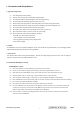
1. Precautions and Safety Notices 1. Appropriate Operation (1) (2) (3) (4) (5) (6) (7) (8) (9) (10) Turn off the product before cleaning. Use only a dry soft cloth when cleaning the LCD panel surface. Use a soft cloth soaked with mild detergent to clean the display housing. Use only high quality and safety approved AC/DC power cord. Disconnect the power plug from AC outlet if the product is not used for a long period of time.
(11) After installation of the TFT Module into an enclosure (LCD monitor housing, for example), do not twist nor bend the TFT Module even momentary. At designing the enclosure, it should be taken into consideration that no bending/twisting forces are applied to the TFT Module from outside. Otherwise the TFT Module may be damaged. (12) Cold cathode fluorescent lamp in LCD contains a small amount of mercury. Please follow local ordinances or regulations for disposal.
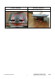
Correct methods : Incorrect Methods : Only touch the metal-frame of the panel or the front cover of the monitor . Do not touch the surface of the polarizer . Surface of the panel is pressed by fingers & this may cause “ MURA “ Take out the monitor with cushion Take out the monitor by grasping the LCD panel. That may cause “ MURA“.
Correct Methods : Incorrect Methods : Place the monitor on a clean & soft foam pad . Place the monitor on foreign objects .
2.
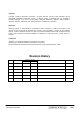
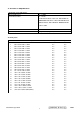
l ELECTRICAL REQUIREMENT Horizontal / Vertical Frequency Horizontal Frequency Vertical Refresh Rate 24 – 82 KHZ 50 – 85* HZ. * FOR RESOLUTION 1280 X 1024, THE VERTICAL REFRESH RATE UP TO 75 HZ; FOR THE REST OF RESOLUTIONS, THE VERTICAL REFRESH RATE UP TO 85HZ Maximum Pixel Clock Sync Polarity 135 MHz Independent of sync polarity. l Timing Table Item 1 2 3 4 5 6 7 8 9 10 11 12 13 14 15 16 17 18 19 20 21 22 23 24 25 26 Timing 640 x 350 @ 70Hz, 31.5kHz 640 x 400 @ 60Hz, 31.5kHz 640 x 400 @ 70Hz, 31.
l TFT LCD PANEL 1st Source Panel Model number Type Active Size Pixel Arrangement Pixel Pitch GLASS TREATMENT # OF BACKLIGHTS BACKLIGHT LIFE Luminance (5-point) – Condition: CT = 6500K, Contrast = Max, Brightness = Max Brightness Uniformity Contrast Ratio Color Depth Viewing Angle (Horizontal) VIEWING ANGLE (VERTICAL) Response Time 10%-90% @ Ta=25°C Panel Defects LPL LM190E03 B4N2/B4N4 TN type with LVDS interface 376.3 (H) x 301.1 (V) RGB Vertical Stripe 0.
l MECHANICAL Dimension (Desktop) Width Height Depth Monitor Weight 431 mm (17 inch) 468 mm (18.4 inch) 201 mm (7.9 inch) 6.7 Kg (14.8 lbs) Dimension (Head Only / Wall Mount) Width Height Depth Monitor Weight 431 mm (17 inch) 370 mm (14.6 inch) 66 mm (2.6 inch) 5.3 Kg (11.
3. Front Panel Function Control Description Adjusting the Screen Image Use the buttons on the front control panel to display and adjust the OnView® controls which display on the screen. The OnView controls are explained at the top of the next page. Main Menu With OnView controls Front Control Panel shown below in detail Scrolls through menu options and adjusts the displayed control. Also a shortcut to display the Contrast adjustment control screen.
Do the following to adjust the screen image: 1 To display the Main Menu, press button [1]. NOTE: All OnView menus and adjustment screens disappear automatically after about 30 seconds. 2 To select a control you want to adjust, press ▲ or ▼ to scroll up or down the Main Menu. 3 After the control is selected, press button [2]. A control screen like the one shown below appears.
Main Menu Controls Adjust the menu items shown below by using the up ▲ and down ▼ buttons. Control Explanation Auto Image Adjust automatically sizes, centers, and fine tunes the video signal to eliminate waviness and distortion. Press the [2] button to obtain a sharper image. NOTE: 1. Auto Image Adjust works with most common video cards. If this function does not work on your LCD display, then lower the video refresh rate to 60 Hz and set the resolution to its pre-set value. 2.
Control Explanation Color Adjust provides several color adjustment modes: preset color temperatures and RGB which allows you to adjust red (R), green (G), and blue (B) separately. The factory setting for this product is 6500K (6500 Kelvin). Color Adjust SRGB 9300K 6500K 5400K User Color sRGB — sRGB is quickly becoming the industry standard for color management, with support being included in many of the latest applications.
Control Explanation Information displays the timing mode (video signal input) coming from the graphics card in your computer. See your graphic card’s user guide for instructions on changing the resolution and refresh rate (vertical frequency). NOTE: VESA 1280 x 1024 @ 60 Hz (recommended) means that the resolution is 1280 x 1024 and the refresh rate is 60 Hertz. Information H. Frequency: V. Frequency: Pixel Clock: Resolution: Model No. : Serial No. : 31.47 KHz 31.47 Hz 24.80 MHz 640 x 480 www.viewsonic.
Control Explanation Setup Menu displays the menu shown below. Setup Menu Language Select Resolution Notice OSD Position OSD Time Out OSD Background 1: Exit The Setup Menu controls are explained below: Language allows you to choose the language used in the menus and control screens. Resolution Notice displays the Resolution Notice menu shown below. Resolution Notice advises the optimal resolution to use. OSD Position allows you to move the on-screen display menus and control screens.
4. Circuit Description 1. Outline 1.1 POWER On/Off , LED, Button"2" , Up arrow- button , Down arrow button , Button"1" , button , Down arrow button , Button"1" , on the front panel. 1.2 Video signal connector, and AC-IN are located on the back side of the cabinet. 1.3 OSD menu includes the following function; AUTO IMAGE ADJUST CONTRAST / BRIGHTNESS COLOR ADJUST INFORMATION MANUAL IMAGE ADJUST SETUP MENU MEMORY RECALL 1.4 CONTRAST and BRIGHTNESS can be directly controlled with UP / DN key. 2. CONNECTORS 2.
3. ELECTRICAL SPECIFICATIONS 3.1 Standard conditions Display Area 338 x 270 mm Video Signal 0.7 Vpp Contrast 70% Brightness Max. Ambient 20 +/- 5 °C Input AC Warming up > 30 min Display 1280 x 1024 3.2 POWER 3.2.1 Power supply Input Voltage 90 -240 ~Volts Power Frequency 50/ 60 Hz +/-3Hz Input current <1.5Arms @ 90Vac <0.75Arms@240Vac Inrush current 90A(max.) at 230Vac Power consumption 50Watt Output Voltage @0-3.0A load 12Vdc +/-5% 3.2.
5.
(25 -34) CHROMA INFO: Red X - 0.639 Green X - 0.297 Blue X - 0.146 White X - 0.313 Red Y - 0.342 Green Y - 0.615 Blue Y - 0.068 White Y - 0.
______________________________________________________________________ (72-89) Detailed Timing / Descriptor Block 2: Monitor Serial Number: PCN040100001 ______________________________________________________________________ (90-107) Detailed Timing / Descriptor Block 3: Monitor Range Limits: Min Vertical Freq - 50 Hz Max Vertical Freq - 85 Hz Min Horiz. Freq - 30 KHz Max Horiz.
Digital EDID Time: 08:18:48 Date: Tue Jun 29, 2004 ______________________________________________________________________ VIEWSONIC CORPORATION EDID Version # 1, Revision # 3 DDCTest For: ViewSonic VX912 ______________________________________________________________________ 128 BYTES OF EDID CODE: 0 1 2 3 4 5 6 7 8 9 ________________________________________ 0 | 00 FF FF FF FF FF FF 00 5A 63 10 | 1A 8D 01 01 01 01 01 0E 01 03 20 | 80 26 1E 78 2E A2 65 A3 57 4C 30 | 9D 25 11 50 54 BF EF 80 81 80 40 | 71 4F
(25-34) CHROMA INFO: Red X - 0.639 Green X - 0.297 Blue X - 0.146 White X - 0.313 Red Y - 0.342 Green Y - 0.615 Blue Y - 0.068 White Y - 0.
______________________________________________________________________ (72-89) Detailed Timing / Descriptor Block 2: Monitor Serial Number: PCN040100001 ______________________________________________________________________ (90-107) Detailed Timing / Descriptor Block 3: Monitor Range Limits: Min Vertical Freq - 50 Hz Max Vertical Freq - 85 Hz Min Horiz. Freq - 30 KHz Max Horiz.
6. THEORY OF OPERATION This section describes the function of the LCD monitor per functional block. This monitor includes MB board, power board and button board. 6.1 MB BOARD The MB board is a two-layer, single-landed design with ground and internal planes provided. DC power from the power board enter the board through a 6P connector. Other connector on the board is for button board .The VGA cable is a signal cable that contains video signal, sync signal and DDC signal from PC VGA adapter.
3 P5.0 LCD panel power2 on / off control 36 P4.0 Backlight on / off control e) Panel Power Sequencing ( VDDCTRL1, 2) ( Pin 32, 3) : The MTV312 has two dedicated outputs VDDCTRL1 and 2 ( Pin32 and Pin3) to control LCD power sequencing once data and control signals are stable. f) Panel interface (Pin 1~25, Pin75~128) : The MTV312 driver interface is highly programmable. It supports dual bus / dual port for SXGA drivers. 6.1.
5. Adjusting Procedure OSD Function Menu 1. Main Menu Press “1” Button (Menu Button) to enter Main Menu: Press Up Button to the previous page or Down Botton to the next page . Press “1” Button to exit Main Menu. (1) Auto Image Adjust Page: Press “2” Button to do auto imag e adjust function. Press “1” Button to exit the page. (2) Contrast/Brightness Page: Press “2” Button to enter Contrast Item. Press “1” Button to exit the page. 1) Contrast Item Press Up Button to make contrast high.
(5) Manual Image Adjust Page: Press “2” Button to enter Manual Image Adjust page. Press “1” Button to exit Manual Image Adjust page. Press Up Button to the previous item or Down Botton to the next item. 1) H./V. Position Item Press “2” Button to enter H./V. Position item. Press “1” Button to exit H./V. Position item. a) Horizontal Position Option: Press “2” Button to enter the Vertical Position option. Press “1” Button to exit Horizontal Position option. Press Up Button to make current option high.
2) Resolution Notice Item Press “2” Button to enter Resolution Notice item. Press “1” Button to exit Resolution Notice item. Enable, Disable Option Press “2” Button to select the option. Press “1” Button to exit the option Press Up Button to the previous option or Down Botton to the next option. 3) OSD Position Item Press “2” Button to enter OSD Position ite m. Press “1” Button to exit OSD Position item. a) Horizontal Position Option Press “2” Button to enter the Vertical Position option.
3. Function test (1) Test equipment Color video Signal & pattern generator (or PC with SXGV resolution ) (2) Test condition Warm-up at least 30mins is necessary under following condition before function test & alignment : 1. room temperature 2. With full-white screen , RGB , black pattern 3. with cycled display modes. 4. Test display modes Item Timing Analog 1 640 x 350 @ 70Hz, 31.5kHz Yes 2 640 x 400 @ 60Hz, 31.5kHz Yes 3 640 x 400 @ 70Hz, 31.5kHz Yes 4 640 x 480 @ 50Hz, 24.
5. Test pattern Item 1 2 Test condition Frequency & performance Monitor saturation Pattern Cross-hatch pattern 16-gray scale pattern 3 RGB color performance RGB color 4 Sub-pixel defect RGB color 5 Full white Full white 6 7. 8.
Pattern 5 Pattern 6 Pattern 7 Pattern 8 Pattern 9 Confidential - Do Not Copy ViewSonic Corporation 30 VX912
6. Firmware update procedure : When you received a received monitor , please check whether the firmware version. If not , please following procedure to upgrade to the latest version . 1.
2. Connection : To Monitor To PC Appendix A : How to install the software for ISP : 1. To setup ISP environment : Hardware: PC or notebook, parallel(printer) cable, ISP tooling. Software: If OS was Win2000 or WinXP , please install “PORT95NT.exe” In order to ensure can execute ISP program, please set BIOS in PC or Notebook as Fig 0.0 Fig 0.
2. Double-click the “ PORT95NT.exe” in Windows & install the program. , see Fig 0.1 Fig 0.1 3. Keep on press “ Next “ 4 times to go through the installation processes, see Fig. 0.2 Fig. 0.
4. Choose “ Typical “ then press “ Next “ , see Fig. 0.3 Fig. 0.3 5. Keep on press “ Next “ 4 times to go through the installation processes, see Fig. 0.4 Fig. 0.
6. Install completed , restart the PC or notebook. See Fig 0.5 Fig. 0.5 Install ISP 1. User could download ISP driver and PORT95NT install from Myson Century website (www.myson.com.tw ) 2. After extracting the ZIP file , the total files list as Fig 1.0 , and double click the file of setup.exe to install. Fig 1.
3. Press “ Next “ button to continue., see Fig 1.1 Fig 1.1 4. Keep default setting or press “ Change “ button for selecting to continue , see Fig 1.2 the path that you want , and then press “ Next “ button Fig 1.
5. Press “ Install “ button to continue , see Fig 1.3 Fig. 1.3 6. Installation has finished , press “ Finish “ button , see Fig 1.4 Fig. 1.
Appendix B : How to use software to upgrade the BIOS : 1. After installation , we could find the shortcut in the setting path or the program bar ( default setting ) , see Fig 2.1 Fig. 2.1 2. Security file is a key to use ISP function , press “ OK “ button , see Fig 2.2 Fig. 2.2 3. The warning is used to remind user of that different CPU rate may cause ISP function fail. (it’s limited by IIC protocol ) , press “ OK “ button , see Fig 2.3 Fig. 2.
4. Press “ Create Security File “ button to key in Security code . Adjusting bar to decrease speed of IIC bus , See Fig. 2.4 . Speed of IIC bus Security code Fig. 2.
5. Fig 2.5 shows the setting for security code of software ISP . it needs 2 command No. and key in command sequentially for 7C , 4C , 77. The command No. and command must be set by user while coding. About the detailed of setting , please refer to section 6 boot code of ISP . Fig. 2.
Appendix C : Use ISP to program MCU 1. Select MTV type first , load the binary or intel hex file that you want to program into the MCU , and select “ AUTO” item , then press “ RUN “ button , see fig3.1 Step 2 Step 1 Step 3 Step 4 Fig. 3.
2. If user change the MTV type , it must load file again , or the buffer of load file will be cleared . 3. CRC ( cyclic redundancy check ) : the host can check CRC register’s result instead of reading every byte in flash . The message of Check MCU CRC OK means that the host verify OK for the progress of program , see Fig.3.2 Fig. 3.
6. Trouble Shooting Flow Chart 1.
2.
7. Recommended Spare Parts List RECOMMENDED SPARE PARTS LIST (VX912) ViewSonic Model Number: VX10162 Rev: 1b Item Description PC Board Assembly: 1 2 3 4 Cabinets: 5 6 7 8 9 10 11 Cables: Documentation: 12 13 14 15 16 17 18 19 20 Electronic Hardware: Miscellaneous: Packing Material: ECR/ECN Power board main board Power board L7VD B/B S/P (DONG KUAN) Front bezel assy Stand cover rear I/O COVER L9V(EBL9V003,REV3A) back cover assy Stand base ass'y Cable for MB-LCD (30P. Rev.
ViewSonic Model Number: VX10162 Rev: 1a Level BOMS LIST (VX912-1) Part Number Part Description Qty Location 0 VX912 1L9VDZLVS12 L9V LCD MONITOR(L9VD,LG VX912)USA 1 #N/A 29L7VMB00T3 L7VD M/B ASSY(FOR L9V) VX912 1 2 #N/A 3BL7VSS0033 L7VD M/B S/S ASSY(FOR L9V) 1 2 #N/A CC62204MD23 CAP ELEC 22U 25V(+-20%,105C,5*11,2000HR) 7 C17,C25,C28,C30,C33,C36,C49 2 #N/A CC73303MD51 CAP ELEC 330U 16V(+-20%,105C,8*11,2000HR 2 C58,C79 2 #N/A CC71004MD68 CAP ELEC 100U 25V +-20%,105C,6*11,LESR
8.
EXPLODED PARTS LIST (VX912-1) ViewSonic Model Number: VX10162 Rev: 1a Item ViewSonic P/N Ref.
Packing for shipping PACKING PARTS LIST (VX912-1) Rev: 1a Item 1 2 3 4 5 6 7 8 Confidential - Do Not Copy ViewSonic Corporation 49 VX912 Viewsonic P/N M-00000265 P-FM-0602-0896 P-FM-0602-0897 DC-00000264 A-PC-0106-0224 P-BX-0601-1085 M-LB-0813-1042 M-MS-0808-9817 Ref. P/N 1L9VDZLVS12 HBL9V001019 HBL9V002015 HGL9V002010 DM333181G97 HFL9V003015 HCL7V019011 HAL9V002014 Description VX912 LCD monitor End-cap (L) End-cap (R) User menual & CD ROM Power cord 3P 1.
Packing procedure 1. Paste protection film to protect the monitor. 2. Put the monitor in EPE bag & seal the with tape 3.
4. Put the monitor into carton & put all the accessories into the carton . Then close the carton. QSG Power cord Disassemble monitor 1. Turn the monitor , face to back-side & take the I/O cover off 2.
3. Remove the 4pcs of black hinge screw & separate the stand & head part 4. Face-down & put the monitor on soft surface of desktop 5.
6. Remove the screws which for fixed the B/B & pull the cable out from the connector on M/B 7. Remove the B/B 8.
9. Remove the MB-LCD connector & loosen the 4 screws on PCB holder Screws 10.
11. Loosen the 4 screws on the sides of panel 12.
13. Remove the 4 hexagon screws beside the DVI & D-sub connector 14.
9. Block Diagram 9.
9.
+3.3V+2.5V RSDS AND LVDS DVI SCALAR MST8131A/MST8136A ANALOG RGB POWER LCDPWR_ON3.3V +3.3V +3.3V EEPROM 24LC16 LCDVCC LCDPWR_ON12V PC VGA PANEL(17,19 RSDS OR LVDS) +3.3V +12V AUDIO_MUTE AUDIO_VOLUME BRIGHTNESS AC 90-264V INVCTRL MICRO-CONTROLLER MTV312 DDC POWER INVERTER AND AUDIO BOARD +12V AIC1563 +5.0V AIC1117AIJ +2.5V +3.
10. Schematic Diagrams RED+IN VGA_SDA_O 2 11 DDC-SDA 12 IN-H 13 IN-V 14 DDC-SCL 15 PAGE1 VGA INPUT RED-IN GREEN-IN BLUE-IN IN-H VGA_CON_O VGA_SCL_O DSUB_5V_O L35 + + + + + + + + + + + + + + RED-IN NC R3 75/6/F 0.047u/6 C3 0.047u/6 C4 0.047u/6 C6 0.047u/6 C7 0.01U/6 C8 0.
VAD VPLLVDVI VDPLL VPO VDD 63 62 60 59 61 58 57 37 38 29 28 RED+ REDGREEN+ GREENSOGIN BLUE+ BLUEHSYNC VSYNC 3 3 3 3 3 3 3 3 TX2+ TX2TX1+ TX1TX0+ TX0TXC+ TXC- R27 VDVI 390/6 1% 40 41 43 44 46 47 49 50 52 18 87 97 117 R+ RG+ GB+ BCK+ CKREXT C103 L8 VPO CX601T02001/8 VDDC VDDC VDDC VDDC 11 21 84 94 104 114 126 53 45 51 35 RIN0 RIN0M GIN0 GIN0M SOGIN0 BIN0 BIN0M HSYNC0 VSYNC0 DDC1_CLK/GPO8 DDC1_DAT/GPO7 VDDP VDDP VDDP VDDP VDDP VDDP VDDP AVDD_PLL 3 3 3 3 3 3 3 3 3 AVDD_DVI AVDD_DVI
VCPU VDD3V3 VDD3V3 NC R59 22/6 SS0003 4 INT C52 22P/6 R60 100/6 X2 11.0592MHz 37 36 P4.1/HBLANK P4.0/VBLANKK 19 P3.2/INT0 15 P4.2/STOUT 11 X2 12 NC NC P6.3/AD3 P6.2/AD2 P6.4/DA10 P6.5/DA11 P5.3/DA3 P5.4/DA4 P5.5/DA5 HALFV/DA8 42 41 40 39 VSS 10 X1 VDDCTRL_2 6 VDD3V3 VDD3V3 10K/6 10K/6 0/6/NC CN5 4 3 2 1 SCL-VGA SDA-VGA VDDCTRL_1 6 RESET 4 VCPU NC VDD3V3 HP-MCU 3 LED_R LED_G D36 STBY 7 VCPU 10K/6 C95 C94 C93 2.
LCDVDD VCC12 CN9 +5V BR1P BR0P LVB2M GND BCLKP FCLKN FB0N GND FB1N FB2N LVACKM FG0N Q6 SI2301DS VDD3V3 4 LVB2M LCDVDD 3 R103 R104 C75 0/8/NC 0.1U/6/NC 330U/16V/NC 1 4 LVACKM R74 3 C76 C77 2200P/6 G2 D VDDCTRL_1 5 82K/6 2 0.1U/6 330U/16V GND LCDVCC BR1N BR0N LVB2P GND BCLKN FCLKP FB0P GND FB1P FB2P LVACKP FG0P POL LCDVCC LCDVCC LVB2P 4 LCDVCC R81 3.6K/F/6/NC LVACKP 4 R82 1.
VCC12 AR2 10K/6/NC AR3 AR4 3.9K/6/NC AQ4 2N3904/NC VOLU VCC12 1 2K/6/NC 2 AC1 AR15 4 VOLUME 10K/6/NC 1U/8/NC 1K/6/NC 3 AR1 AL1 AC2 PC AUDIO-IN 0.47U/8/NC 10K/6/NC AR12 10K/6/NC 16 VAROUT_L AC5 SPKOUTL 330U/16V/NC 5 ACN1 CX201209805/8/NC 1 2 3 CX201209805/8/NC 4 VOLUME 6 7 VOLU AR10 11 STBY VAROUR_R 12 MUTE OUTR 10 SVR 14 AC9 AL5 SPKOUTR 330U/16V/NC BEAD/1206/NC TDA7496L/NC AGND AL6 BEAD/1206/NC 1 DTC144EUA/NC AC11 330U/16V/NC AQ2 2 AC10 0.
D1 1SS355 C57 1u/8 5 6 7 8 U21 R63 0/1206 VCC12 2 C59 C63 C58 330u/16V 0.1u/6 BOOST DC 1 7 IS DE 2 6 VCC CF 3 5 FB GND 4 0.1u/6 Q13 R17 47/6 R16 C102 120p/6 AIC1563 330K/6 D9 1SS355 NDS9410A/SO FUSE1 0/1206 1 8 4 3 2 1 12Vin C67 0.1u/6 R79 240K/6 1% Q17 MMST3906 R66 +5V R78 1K/6 3K/6 1% L21 L33 1 CX000800000/1206 D26 2 RB081L-20 C62 1000u/6.3V 47UH 1 1K/6 1% 2 2200p/6 C61 0.
11.
*Readers Response* Dear Readers: Thank you in advance for your feedback on our Service Manual,which allows continuous improvement of our products. We would appreciate your completion of the Assessment Matrix below, for return to ViewSonic Corporation. Assessment A.What do you think about the content after reading VX912 Service Manual? U nit Ex cellent Fair G ood Bad 1. Precautions And Safety Notices 2. Specification 3. Front Panel Function Control Description 4. Circuit Description 5.