Contents Product Registration......................................................………..............................….........2 Important Product Safety Instructions ................................................…............................3 Antenna Installation Instructions ........................................ .............................……………4 Cleaning the LCD ..............................................................................................….............
Copyright © ViewSonic Corporation, 2004. All rights reserved. Macintosh and Power Macintosh are registered trademarks of Apple Computer, Inc. Microsoft, Windows, Windows NT, and the Windows logo are registered trademarks of Microsoft Corporation in the United States and other countries. ViewSonic, the three birds logo, OnView, ViewMatch, and ViewMeter are registered trademarks of ViewSonic Corporation. VESA is a registered trademark of the Video Electronics Standards Association.
Important Product Safety Instructions Attention: Follow and obey all warnings and instructions marked on your product. For your safety, please read all the safety and operating instructions before you operate this product. Keep this user guide for future reference. Installation 1 Grounding or Polarization Your product may be equipped with a polarized alternating-current line plug (a plug having one blade wider than the other). This plug will fit into the power outlet only one way. This is a safety feature.
Antenna Installation Instructions 1 Outdoor Antenna Grounding If an outside antenna or cable system is connected to the product be sure the antenna or cable system is grounded to avoid voltage surges and built-up static charges.
Getting Started Congratulations on your purchase of a ViewSonic LCD TV display. Important! Save the original box and all packaging material for future shipping needs.
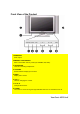
Front View of the Product 1.SPEAKERS Audio output. 2.MEMORY CARD READER Slots to insert flash memory cards (CF, SD/MMC, MS, SMC). 3. HEADPHONE Used for connecting headphones. 4. SOURCES Switch between display input sources. 5. MENU Display menu screen. HEADPHONE MENU VOL CH POWER SOURCES CF 6. VOL +/– UsedSM forMS changing the volume. SD/MMC 4 7. CH ▼ /▲ Changes the channel. 8. POWER 5 8 Turns 7 6the TV on and off. A green light indicates that TV is on and red that it is off.
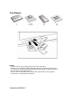
Card Reader NOTES: • Insert the memory card according to the arrow on the card’s label. • The device can only display digital graphic files, which are stored on the memory card (ie. JPEG files). The device supports all JPEG formats as created by digital cameras, but does not support other graphic formats. • You can insert CF, SD, MMC, SMC, and MS cards. Other cards are not supported. • Two cards can not be used at the same time.
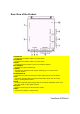
Rear View of the Product R ANT 1 L 1.SCART1-IN Connects to the SCART output of your A/V device. 2.SCART2-IN Connects to the SCART output of your A/V device. 3.DVI IN Connects to the DVI output of your PC or portable computer. 4.PC AUDIO IN Supports DVI input and VGA input. 5. VGA IN Connects to a computer’s VGA out jack, enabling you to use the TV as a computer monitor. 6.COMPONENT IN Connects to the audio and component video output jacks of your A/V device. 7.
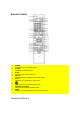
Remote Control 1. 2. POWER Turns power on or to standby mode. S-VIDEO 3. SLEEP 4. CH▼/ ▲ Decreases ▼ or increases ▲ the channel number. VOL –/+ Increases (+) or decreases (–) the volume. Switches to S-Video input. Sets the time to turn off the unit. 5. 6. 7. 8. Switches to the previously viewed channel. TELETEXT HOT KEYS Select groups of pages in teletext mode. INDEX Displays a list and information about the teletext pages.
9. 10. 11. 12. 13. 14. 15. 16. 17. 18. 19. 20. 21. 22. 23. 24. 25. 26. 27. 28. 29. 30. SUB PAGE Displays the teletext sub page. ZOOM Zoom enlarges the teletext page; Hold freezes the current teletext page on the screen. VIDEO MUTE Turns off the video display. The TV screen turns blank. ARROW KEYS Press the up, down, left, right arrow keys to scroll through the OSD menu options. MENU Displays the OSD menu. Press repeatedly to view the different menu pages or exit the OSD menu.
31. - /- Press to type in a channel number up to 99. 32. NUMBER KEYS Press the number keys to enter channel numbers. 33. TV Switches the source to TV mode. 34. AV Switches the source to AV (Composite) mode. 35. DISPLAY Press repeatedly to display current time, channel number, or video input signal. 36. MUTE Disables the audio output. Notes • The remote control’s effective range is 5 meters from the LCD screen at an angle of up to ±30°. • Direct light may affect the remote controls effective range.
Installation Attaching the Speaker Follow these steps to attach the speakers. 1 Attach one part A and a speaker to one side of the LCD TV with screws as shown in the illustration. 2 Secure one part B to part A with screws as shown. 3 Repeat these steps to attach the second speaker. Attaching the AV Tuner Box The AV Tuner Box generally has pre-installed on the LCD TV. Please follow these steps for installation otherwise. 1 Slide part A upwards, then remove.
Remote Control Battery Installation Follow the steps below to insert the batteries. 1 Open the remote control’s rear battery compartment cover. 2 Insert two AAA batteries. Ensure that the positive and negative ends match as indicated on the bottom of the battery compartment. 3 Replace the battery compartment cover. CAUTION • Only use the specified AAA batteries. • Do not mix new and old batteries. This may result in cracking or leakage, which may pose a fire risk or lead to personal injury.
Cable Connections Attach video and audio cables according to the connections on your external devices such as DVDs, VCR’s, stereo systems. Power Cable Connection 1 Connect the power cable to a wall socket. 2 Connect the other end to the socket on the back of the LCD TV Turning the TV (Power) On 1 Press the power button. The power light will turn from red to green and the screen will appear after 5 seconds. 2 Press the power button again to turn it off.
OSD Functions All the functions for the LCD TV are controlled either by the remote control or the control buttons on the front control panel at bottom of the TV. See “Front View of the Product” on page 6. Press the MENU button on the remote control or the front control panel to display the OSD main menu. Press the MENU button to select the OSD menu you want. Press the ◄ / ► buttons to select an OSD menu item.
Source Input: TV/AV/S-Video/SCART Image Adjustment Function Name BRIGHTNESS Contrast Color Tint Sharpness Video Mode Explanation Brightness adjustment. Contrast adjustment. Color adjustment. Tint adjustment. Sharpness adjustment. Select TV image display: Preset: Factory default settings. Soft: Picture settings result in softer colors and less sharp images. User: User defined settings.
Audio Adjustment The Audio menu enables you to configure the volume, treble, and bass of the audio output. Use the slider bars to adjust these settings. Function Name Volume Treble Bass Balance Audio Mode Speaker SOUND Explanation Adjusts the overall volume of the speakers. Adjust Treble Level. Adjust Bass Level. Adjust left and right speaker balance. Stores Audio settings. Soft: audio settings that result in softer audio. User: user defined settings.
Settings Menu ViewSonic N3200w 18
Screen Setting Function Name Explanation PIP Enables and disables PIP (Picture-in-Picture) mode. PIP Position Moves the mini-screen to one of the screen's four corners. Source Switch between using TV/SCART1&2/AV/S mode and YPbPr/RGB/DVI mode for the main screen. POP Enables and disables POP (Picture-on-Picture) mode. Swap Swaps the input sources between main and sub screens display. i.e. When in the POP mode, only the subtitles and audio input are swapped. Screen Mode Enables you to select a screen mode.
TV settings Function Name Program Fine Tune Manual Scan Skip Name Save Tuner System Explanation Indicated the program/channel number when it scanned. Display the selected frequency and change the frequency for the channel. Scan the available channels by pressing - /◄ or + / ►. Enable to delete the current channel To edit the name of scanned channel/program. Save the setting of PR EDIT. Note: If all setting without actives "Save", then changes in PR EDIT setting will back to the default setting.
ViewSonic N3200w 21
Color settings Function Name Red Green Blue Color Temperature Explanation Adjusts the red color Adjusts the green color Adjusts the blue color Adjust the color temperature from Cool, Warm, Nature, and User.
Source Input: PC Function Name BRIGHTNESS CONTRAST SHARPNESS H POSITION V POSITION PHASE CLOCK AUTO Explanation Brightness adjustment. Contrast adjustment. Sharpness adjustment. Adjust horizontal position on the image. Adjust vertical position on the image. Adjust the phase of screen to obtain the best output. Adjust screen’s horizontal size. Automatically adjusts the screen according to the input signal source.
Source Input: DVI-D Function Name BRIGHTNESS CONTRAST SHARPNESS H POSITION V POSITION AUTO Explanation Adjust the white level of the screen. Adjust the black level of the screen. Adjust the sharpness level of the screen. Adjust the screen’s horizontal position. Adjust the screen’s vertical position. Auto adjusts, the phase, clock, and position of the image.
Appendix Specifications Panel Type 32” (full 32” viewable diagonal area), TFT (Thin Film Transistor), Active Matrix WXGA LCD, 1280RGB * 768 vertical stripe Color Anti-reflective Viewing angles Input signal coating + Anti-glare coating 170° (H) / 170° (V) Audio RGB Analog * 1 (75 ohms, 0.
Troubleshooting No power • Make sure the LCD is properly connected. (see also pages 12-14) • Make sure the AC power cord is properly connected. (see also page 14) • Make sure the AC power is ON, DC power button is ON (Green LED). • Plug another electrical device (like a radio) to the power outlet to verify that the outlet is supplying the proper voltage. Poor or no picture • The TV station may be experiencing problems. Try another channel. • The Cable TV signal may be scrambled or encoded.
ViewSonic N3200w 27
Limited Warranty VIEWSONIC LCD TV DISPLAY What the warranty covers: ViewSonic® warrants its products to be free from defects in material and workmanship during the warranty period. If a product proves to be defective in material or workmanship during the warranty period, ViewSonic will, at its sole option, repair or replace the product with a like product. Replacement product or parts may include remanufactured or refurbished parts or components.
Safety Guidelines Warning: This device must be operated with the original power supply, part number: 12VDC LSE9901B1250, 12VDC UP06031120. CAUTION: The socket-outlet should be installed near the equipment and should be accessible. CAUTION: Use a power cable that is properly grounded. Always use the appropriate AC cord that is certified for the individual country. Some examples are listed below: USA................UL Canada ..........CSA Germany ........VDE Switzerland .…SEV Britain..............