Service Manual ViewSonic VX922-1 Model No. VS10162 19” Color TFT LCD Display (VX922-1_SM Rev. 1c Nov.
Copyright Copyright ¤ 2006 by ViewSonic Corporation. All rights reserved. No part of this publication may be reproduced, transmitted, transcribed, stored in a retrieval system, or translated into any language or computer language, in any form or by any means, electronic, mechanical, magnetic, optical, chemical, manual or otherwise, without the prior written permission of ViewSonic Corporation.
TABLE OF CONTENTS 1. Precautions and Safety Notices 1 2. Specification 5 3. Front Panel Function Control Description 12 4. Circuit Description 18 5. Adjustment Procedure 28 6. Troubleshooting Flow Chart 78 7. Recommended Spare Parts List 84 8. Exploded Diagram and Exploded Parts List 86 9. Block Diagram 89 10. Schematic Diagrams 91 11.
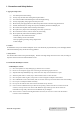
1. Precautions and Safety Notices 1. Appropriate Operation (1) (2) (3) (4) (5) (6) (7) (8) (9) (10) Turn off the product before cleaning. Use only a dry soft cloth when cleaning the LCD panel surface. Use a soft cloth soaked with mild detergent to clean the display housing. Use only a high quality, safety approved AC/DC power cord. Disconnect the power plug from the AC outlet if the product will not be used for a long period of time.
(11) After installation of the TFT Module into an enclosure (LCD monitor housing, for example), do not twist or bend the TFT Module even momentarily. When designing the enclosure, it should be taken into consideration that no bending/twisting forces may be applied to the TFT Module from outside. Otherwise the TFT Module may be damaged. (12) The cold cathode fluorescent lamp in the LCD contains a small amount of mercury. Please follow local ordinances or regulations for disposal.
Correct methods : Incorrect Methods : Only touch the metal frame of the panel or the front cover of the monitor. Do not touch the surface of the polarizer . If the surface of the panel is pressed by fingers, this may cause "MURA." Take out the monitor by grasping the cushion. If the monitor is removed by grasping the LCD panel, that may cause "MURA.
Correct Methods : Incorrect Methods : Place the monitor on a clean & soft foam pad . ViewSonic Corporation If the monitor is placed on foreign objects, that could scratch the surface of the panel.
2.
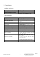
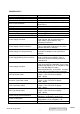
POWER SUPPLY Internal Power Supply Input Voltage Range Input Frequency Range Short Circuit Protection Over Current Protection Leakage Current EFFICIENCY Fuse Power Dissipation Max Input AC Current INRUSH CURRENT (COLD START) Power Supply Cold Start Power Supply Transient Immunity Power Supply Line Surge Immunity Power Supply Missing Cycle Immunity Power Supply Acoustics US Type Power Cable European Type Power Cable CCC Type Power Cable PSE Type Power Cable Power Saving Operation(Method) Power Consumptio
ELECTRICAL REQUIREMENT Horizontal / Vertical Frequency Horizontal Frequency Vertical Refresh Rate Maximum Pixel Clock Sync Polarity 30 – 82 KHZ 50 – 75 HZ 135 MHz Independent of sync polarity. Timing Table Item Timing 1 640 x 350 @ 70Hz, 31.5kHz 2 640 x 400 @ 60Hz, 31.5kHz 3 640 x 400 @ 70Hz, 31.5kHz 4 640 x 480 @ 50Hz, 24.7kHz 5 640 x 480 @ 60Hz, 31.5kHz 6 640 x 480 @ 67Hz, 35.0kHz 7 640 x 480 @ 72Hz, 37.9kHz 8 640 x 480 @ 75Hz, 37.5kHz 9 640 x 480 @ 85Hz, 43.27kHz 10 720 x 400 @ 70Hz, 31.
Panel Characteristics: st 1 Source Panel Model number Type Active Size Pixel Arrangement Pixel Pitch GLASS TREATMENT # OF BACKLIGHTS BACKLIGHT LIFE Luminance (5-point) – Condition: CT = 6500K, Contrast = Max, Brightness = Max Brightness Uniformity Contrast Ratio Color Depth Viewing Angle (Horizontal) Viewing Angle (Vertical) Response Time 10%-90% @ Ta=25°C Panel Defects ViewSonic Corporation CPT CLAA190EA05Q TN type with LVDS interface 372 (H) x 302 (V) RGB Vertical Stripe 0.
2 nd Source Panel Model number Type Active Size Pixel Arrangement Pixel Pitch GLASS TREATMENT # OF BACKLIGHTS BACKLIGHT LIFE Luminance (5-point) – Condition: CT = 6500K, Contrast = Max, Brightness = Max Brightness Uniformity Contrast Ratio Color Depth Viewing Angle (Horizontal) Viewing Angle (Vertical) Response Time 10%-90% @ Ta=25°C Panel Defects ViewSonic Corporation HSD HSD190ME13-D10 TN type with LVDS interface 376.32 (H) x 301.06 (V) RGB Vertical Stripe 0.
IMAGE PERFORMANCE Factory Defaults Item Contrast Brightness Color Temperature Sharpness 720x400/640x400 Defaults 70% 100% 6500K 33% 720x400 Luminance Lv (Max) – Condition: Contrast = 100% Brightness = 100% Color Temperature = 6500K Lv (Def) – Condition: Contrast = Default Brightness = Default Color Temperature = 6500K Display Size Horizontal Display Size, Primary Preset Vertical Display Size, Primary Preset Saturation Contrast = Default Brightness = Default Test Pattern = 64-Gray Contrast = 100% Brightne
Preset Color Temperatures SRGB Preset 1 9300K It should meet IEC 61966-2-1 (1999-10) standard Wx= 0.283+/- 0.015, Wy= 0.298+/- 0.015 Preset 2 6500K (Primary) Wx= 0.313+/- 0.015, Wy= 0.329+/- 0.015 Preset 3 5400K Wx= 0.335+/- 0.015, Wy= 0.350+/- 0.015 Preset Color Temperature Adjustability Each color preset shall be adjustable. Red, Green, and Blue shall be individually controlled.
3. Front Panel Function Control Description Adjusting the Screen Image Use the buttons on the front control panel to display and adjust the OSD controls which display on the screen. The OSD controls are explained at the top of the next page and are defined in “Main Menu Controls” on page 13. Main Menu with OSD controls Front Control Panel shown below in detail Scrolls through menu options and adjusts the displayed control. Also a shortcut to display the Contrast adjustment control screen.
Do the following to adjust the display setting: 1. To display the Main Menu, press button [1]. NOTE: All OSD menus and adjustment screens disappear automatically after about 30 seconds. This is adjustable through the OSD timeout setting in the setup menu. 2. To select a setting to be adjusted, pressSorTto scroll up or down the Main Menu. 3. After the desired control is selected, press button [2]. A control screen like the one shown below appears.
Main Menu Controls Adjust the menu items shown below by using the upSand downTbuttons. Control Explanation Auto Image Adjust automatically sizes, centers, and fine tunes the video signal to eliminate waviness and distortion. NOTE: 1. Auto Image Adjust works with most common video cards. If this function does not work on your LCD display, then lower the video refresh rate to 60 Hz and set the resolution to its pre-set value. 2.
Control Explanation 6500K-Adds red to the screen image for warmer white and richer red. 5400K-Adds green to the screen image for a darker color. User Color Individual adjustments for red (R), green (G), and blue (B). 1. To select color (R, G or B) press button [2]. 2. To adjust selected color, pressSorT. Important: If you select RECALL from the Main Menu when the product is set to a Preset Timing Mode, colors return to the 6500K factory preset.
Control Explanation The Manual Image Adjust controls are explained below: H./V. Position (Horizontal/Vertical Position) moves the screen image left or right and up or down. H. Size (Horizontal Size) adjusts the width of the screen image. Fine Tune sharpens the focus by aligning the text and/or graphic characters. Sharpness adjusts the clarity and focus of the screen image.
Control Explanation OSD Timeout sets the length of time the on-screen display screen is displayed. For example, with a “15 second” setting, if a control is not pushed within 15 seconds, the display screen disappears. OSD Background allows you to turn the On-Screen Display background On or Off. Memory Recall returns the adjustments back to factory settings if the display is operating in a factory Preset Timing Mode listed in the Specifications of this manual.
4. Circuit Description 1. Outline 1.1 Buttons on the front panel: Power On/Off button, button 2 (ENTER / INPUT SELECT), up arrow button, down arrow button, button 1 (MENU). 1.2 The D-sub 15-pin connector, DVI-I connector and AC-IN jack are located on the back side of the cabinet. 1.3 The OSD menu includes the following functions: Auto Image Adjust (only active under analog input) Contrast/Brightness Audio Adjust Color Adjust Information Manual Image Adjust Setup Menu Memory Recall 1.
2.3 Video signal connector for digital input: 24pin DVI-D connector CN9 RX2RX2+ GND RX4RX4+ SCL SDA VS RX1RX1+ GND RX3RX3+ 5V GND HP RX0RX0+ GND RX5RX5+ GND RXC+ RXC- Pin No. 3. RX2- TMDS negative differential input, channel 2 2 RX2+ TMDS positive differential input, channel 2 3 GND Logic Ground 4 RX4- Reserved. No connection 5 RX4+ Reserved. No connection 6 SCL DDC2B Clock 7 SDA DDC2B Data 8 VS Reserved.
3.2 Power 3.2.1 Power supply Input voltage 100~240Vac Power frequency 50~60Hz Input current <1.5A RMS @90V AC Inrush current <0.8A RMS @180V AC 50A(Max) at 120Vac(cold start) Power consumption 3.2.2 35W(typical);40Watts(Max) Power Management State Power Indicator On 35Watts Green Standby < 1Watts Amber Off <1Watts Off 3.3 Acceptable timing This LCD display can automatically detect and display input signals whose timing falls within the following limits.
5.
(36) ESTABLISHED TIMING II: 800 X 600 @ 72Hz (VESA) 800 X 600 @ 75Hz (VESA) 832 X 624 @ 75Hz (Apple,Mac II) 1024 X 768 @ 60Hz (VESA) 1024 X 768 @ 70Hz (VESA) 1024 X 768 @ 75Hz (VESA) 1280 X 1024 @ 75Hz (VESA) (37) Manufacturer's Reserved Timing: 1152 X 870 @ 75Hz (Apple,Mac II) (38-53) Standard Timing Identification: 1280 X 1024 @60Hz 1152 X 864 @75Hz 1024 X 768 @85Hz 800 X 600 @85Hz 640 X 480 @85Hz Not Used Not Used Not Used ______________________________________________________________________ (54-7
Digital EDID 128 BYTES OF EDID CODE: 0 1 2 3 4 5 6 7 8 9 ________________________________________ 0 | 00 FF FF FF FF FF FF 00 5A 63 10 | 1C 0F 01 01 01 01 01 0F 01 03 20 | 80 26 1E 78 2E 68 75 A2 5A 49 30 | 9F 23 13 50 54 BF EF 80 81 80 40 | 71 4F 61 59 45 59 31 59 31 0A 50 | 01 01 01 01 30 2A 00 98 51 00 60 | 2A 40 30 70 13 00 78 2D 11 00 70 | 00 00 00 00 FF 00 50 53 33 80 | 30 35 30 31 30 30 30 30 31 0A 90 | 00 00 00 FD 00 32 5
(36) ESTABLISHED TIMING II: 800 X 600 @ 72Hz (VESA) 800 X 600 @ 75Hz (VESA) 832 X 624 @ 75Hz (Apple,Mac II) 1024 X 768 @ 60Hz (VESA) 1024 X 768 @ 70Hz (VESA) 1024 X 768 @ 75Hz (VESA) 1280 X 1024 @ 75Hz (VESA) (37) Manufacturer's Reserved Timing: 1152 X 870 @ 75Hz (Apple,Mac II) (38-53) Standard Timing Identification: 1280 X 1024 @60Hz 1152 X 864 @75Hz 1024 X 768 @85Hz 800 X 600 @85Hz 640 X 480 @85Hz 640 X 400 @70Hz Not Used Not Used _____________________________________________________________________
6. THEORY OF OPERATION This section describes the function of the LCD monitor per functional block. This monitor includes MB board, power board and button board. 6.1 MB BOARD The MB board is a two-layer, single-grounded design with ground and internal planes provided. DC power from the power board enters the board through a 6P connector. The other connector on the board is for the button board. The VGA cable is a signal cable that carries the video, sync and DDC signals from the PC VGA adapter.
d) MTV312 Micro Controller: The MTV312 micro controller (MCU) serves as the system micro controller. It programs the RTD2523 and manages other devices in the system such as the keypad, the backlight, the LED, the audio system and the non-volatile RAM using general purpose input/output (GPIO) pins. Pin number Pin Name Pin Usage 1 P5.2 Key / Power on, off 13 P3.4 NV_RAM (U4) SDA 14 P3.5 NV_RAM (U4) SCL 41 P5.4 Key_down 40 P5.5 Key_right 42 P5.3 Key_up 34 P5.6 Key_left 9 P6.
6.2 Power (Inverter) Board This is a specific power (inverter) board for VX912 monitor with output of 40W / 12V / 3.5A. It provides 12 VDC to drive the four cold cathode fluorescence tubes in the backlight. 6.2.1 The inverter's electrical specification is described below. Input Output Rated Input Voltage 12Vdc Input Voltage Range 11.4 ~ 12.6 Vdc Input Current <2A On / Off control Voltage 2~3.
5. Adjustment Procedure OSD Function Menu A. When in Analog Input Mode 1. Main Menu Press the [1] (Menu) button to enter the Main Menu: Press the [▲] button to highlight the previous item or the [▼] button to highlight the next item. Press the [1] (Menu) button to exit the Main Menu. (1) Auto Image Adjust Page: Press the [2] button to execute the auto image adjust function. Press the [1] button to exit the page. (2) Contrast/Brightness Page: Press the [2] button to enter the contrast adjustment page.
(5) Information Page: Press the [2] button to enter the information page. Press the [1] button to exit the information page. (6) Manual Image Adjust Page: Press the [2] button to enter the manual image adjustment page. Press the [1] button to exit the page. Press the [▲] button to highlight the previous item or the [▼] button to highlight the next item. 1) H./V. Position Item Press the [2] button to enter the horizontal/vertical postion adjustment page. Press the [1] button to exit the page.
Press the [1] button to exit the page. Press the [▲] button to highlight the previous item or the [▼] button to highlight the next item. English, French… Option Press the [2] button to select the language. Press the [1] button to exit the page. 2) Resolution Notice Item Press the [2] button to enter the resolution notice page. Press the [1] button to exit the page. Enable, Disable Option Press the [2] button to select the highlighted option. Press the [1] button to exit the page.
2. Other Menu: This “shortcut” menu is directly accessible without bringing up the OSD. (1) Contrast Dialog Press the [▲] or [▼] button to enter the Contrast Dialog. Press the [1] button to exit the Contrast Dialog. Press the [2] button to enter the Brightness Dialog. Press the [▲] button to increase the contrast. Press the [▼] button to decrease the contrast. (2) Brightness Dialog Press the [▲] or [▼] button to enter the Brightness Dialog. Press the [1] button to exit the Brightness Dialog.
1) 2) 3) 4) 5) Press the [1] button to exit the page. Press the [▲] button to highlight the previous item or the [▼] button to highlight the next item. sRGB Item 9300K Item 6500K Item 5400K Item Press the [2] button to select the currently highlighted item. Press the [1] button to exit the currently highlighted item. User Color Item Press the [2] button to enter the user color page. Press the [1] button to exit the page. Red, Green, Blue Options: Press the [2] button to cycle among the colors.
Press the [1] button to exit the page. Enable, Disable Option Press the [2] button to select the highlighted option. Press the [1] button to exit the page. Press the [▲] button to highlight the previous option or the [▼] button to highlight the next option. 3) OSD Position Item Press the [2] button to enter the OSD position adjustment page. Press the [1] button to exit the page. a) Horizontal Position Option Press the [2] button to enter the vertical position adjustment page.
(2) Brightness Dialog Press the [▲] or [▼] button to enter the Brightness Dialog. Press the [1] button to exit the Brightness Dialog. Press the [2] button to enter the Contrast Dialog. Press the [▲] button to increase the brightness. Press the [▼] button to decrease the brightness. (3) Analog/Digital Dialog Press the [2] button to toggle between analog and digital modes. C.
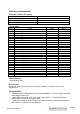
1. Function test (1) Test equipment Color video signal and pattern generator (or PC with SXGA resolution) (2) Test condition Before function testing and alignment, the unit must warm up for at least 30 minutes under the following conditions: 1. Room temperature; 2. With full-white screen, RGB, black pattern; 3. With cycled display modes. 2. Test display modes Item 1 2 3 4 5 6 7 8 9 10 11 12 13 14 15 16 17 18 19 20 21 22 23 24 25 26 Timing 640 x 350 @ 70Hz, 31.5kHz 640 x 400 @ 60Hz, 31.
3. Test pattern Item 1 2 Test condition Frequency & performance Monitor saturation Pattern Cross-hatch pattern 16-gray scale pattern 3 RGB color performance RGB color 4 Sub-pixel defect RGB color 5 Full white Full white 6 7. 8.
Pattern 5 Pattern 6 Pattern 7 Pattern 8 Pattern 9 ViewSonic Corporation 37 Confidential - Do Not Copy VX922-1
6. Firmware update procedure : When examining a monitor, please check whether the firmware version is the latest. If not, please follow the procedure below to upgrade to the latest version. 1.
2. Connection : To Monitor To PC Appendix A : How to install the software for ISP: 1. To set up ISP environment: Hardware: PC or notebook, parallel (printer) cable, ISP tooling. Software: If OS is Win2000 or WinXP, please install "PORT95NT.exe". In order to ensure that the system can execute the ISP program, please adjust the BIOS settings in the PC or notebook as shown in Fig 0.0. Fig 0.
2. Double-click the "PORT95NT.exe" icon in Windows and install the program; see Fig 0.1. Fig 0.1 3. Continue through the installation process by pressing "Next" four times; see Fig. 0.2. Fig. 0.
4. Choose "Typical" then press "Next;" see Fig. 0.3. Fig. 0.3 5. Continue through the installation process by pressing "Next" four times; see Fig. 0.4. Fig. 0.
6. When the installation is complete, restart the PC or notebook; see Fig 0.5. Fig. 0.5 Install ISP 1. The user may download the ISP driver and PORT95NT installation package from the Myson Century website (www.myson.com.) 2. The files extracted from the ZIP file are listed in Fig 1.0. Double-click setup.exe to install. Fig 1.
3. Press the "Next" button to continue; see Fig 1.1. Fig 1.1 4. Press the "Change" button to change the install path if desired, and then press the "Next" button to continue; see Fig 1.2. Fig 1.
5. Press the "Install" button to continue; see Fig 1.3. Fig. 1.3 6. When installation has finished, press the "Finish" button; see Fig 1.4. Fig. 1.
Appendix B: How to use software to upgrade the BIOS: 1. After installation, shortcuts may be found in the settings path or the program menu (default setting); see Fig 2.1. Fig. 2.1 2. The security file is a key to use ISP functions; press the "OK" button. See Fig 2.2. Fig. 2.2 3. The warning shown in Fig. 2.3 is used to remind the user that a CPU rate that differs from IIC protocol may cause the ISP functions to fail; press the "OK" button. Fig. 2.
4. As shown in Fig. 2.4, press the "Create Security File" button to key in a security code, and use the slider bar to adjust the speed of the IIC bus. Speed of IIC bus Security code Fig. 2.
5. Fig 2.5 shows the settings for the ISP software's security code. It requires two command numbers, and the commands must be keyed in sequentially: 7C, 4C, 77. The command numbers and commands must be set by the user while coding. For more details, please refer to section 6 boot code of ISP. Fig. 2.
Appendix C: Using ISP to program MCU 1. As shown in Fig. 3.1, select the MTV type first, load the binary or intel hex file to be programmed into the MCU, click "OK," then press the "RUN" button. Step 2 Step 1 Step 3 Step 4 Fig. 3.
2. If the user changes the MTV type, the file must be loaded again, as the previously loaded file will be cleared. 3. CRC (cyclic redundancy check): the host can check the result in the CRC register instead of reading every byte in flash. The Check MCU CRC OK message indicates that the host has verified the program's CRC; see Fig.3.2. Fig. 3.
EDID update Methods 1. Write Analog DDC Environment setting Please connect VGA cable as bellowing picture. Please must set the monitor in USER mode, not factory mode Open DDC file After installation , we could find the shortcut in the setting path or the program bar ( default setting ) .
Please press , Select Analog DDC file to be loaded Step 1 : Software will pop out a message. Select the Analog DDC file to load.
Check DDC data Check whether the DDC data is loaded in the “TVI_Tool” table.
Write DDC to IC Step 1 : Select “512M” Step 3: Key in the S/N Select “Detailed Timeings” / Select “Block 2” Key in the S/N on the monitor ViewSonic Corporation 53 Confidential - Do Not Copy VX922-1
Step 2 : Press “Write to IC” icon ViewSonic Corporation 54 Confidential - Do Not Copy VX922-1
Step 4: Check the result Write Success : you will see “Compare OK” message in yellow column.
Write Error : If the DDC file write fail, you will see “Write Error” message. Please recheck whether following settings is correct: b.1 : Check the power cable is plug on b.2 : Check the signal cable is correct b.3 : Check you are in USER mode, not in Factory mode b.
2. Write DVI DDC Environment setting Please connect VGA-DVI cable as bellowing picture. Please must set monitor in USER mode , not factory mode Open DDC file After installation , we could find the shortcut in the setting path or the program bar ( default setting ) .
Please press ViewSonic Corporation 58 Confidential - Do Not Copy VX922-1
Select DVI DDC file to be loaded Step 1 : Software will pop out a message. Select the Digital DDC file to load.
Check DDC data Check whether the DDC data is loaded in the “TVI_Tool” table.
Write DDC to IC Step 1 : Select “24C02” ViewSonic Corporation 61 Confidential - Do Not Copy VX922-1
Step 2: Key in the S/N: a) Select “Detailed Timeings” b) Select “Block 2” Key in the S/N on the monitor ViewSonic Corporation 62 Confidential - Do Not Copy VX922-1
Step 2 : Press “Write to IC” icon ViewSonic Corporation 63 Confidential - Do Not Copy VX922-1
Step 3: Check the result Write Success : you will see “Compare OK” message in yellow column.
Write Error : If the DDC file write fail, you will see “Write Error” message. Please recheck whether following settings is correct: b.1 : Check the power cable is plug on b.2 : Check the signal cable is correct b.3 : Check you are in USER mode, not in Factory mode b.
3. Read Analog DDC Environment setting Please use VGA cable as bellowing picture.
Step 2: Check the result a) Read success : you will seed “Read OK” message ViewSonic Corporation 67 Confidential - Do Not Copy VX922-1
b) Read Fail : you will see “ Error Read” message. Please recheck following settings is correct: b.1: Check the power cable is Re-plug on b.2: Check the signal cable is correct and well-plugged b.
4. Read DVI DDC Environment setting Please conntect VGA-DVI cable as bellowing picture.
Step 2: Check the result a) Read success : you will seed “Read OK” message b) Read Fail : you will see “ Error Read” message. Please recheck following settings is correct: b.1: Check the power cable is Re-plug on b.2: Check the signal cable is correct and well-plugged b.
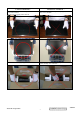
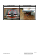
Packing procedure 1. Apply protective film to the display surface. 2. Put the monitor in EPE bag and seal the bag with tape. 3. Fit the cushions onto the monitor.
4. Put the monitor into the carton and put all the accessories into the carton. Then close the carton. QSG Power cord Disassembling the monitor 1. Turn the monitor to face the back and remove the I/O cover. 2. Remove the stand back cover.
3. Remove the four black hinge screws and separate the stand and head pieces. 4. Place the monitor face-down on a soft, flat, stable surface. 5. Separate the back cover and the front bezel.
6. Remove the screws that fix the button board (B/B) and pull the cable out from the connector on the main board (M/B). 7. Remove the B/B. 8. Remove the screws on the PCB shield; remove the PCB shield.
9. Remove the MB-LCD connector and loosen the four screws on the PCB holder. Screws 10. Separate the PCB holder from the panel.
11. Loosen the four screws on the sides of the panel. 12. Remove the front bezel and panel.
13. Remove the four hexagon screws beside the DVI & D-SUB connectors. 14. Remove the screws that fix the power board and main board.
6. Troubleshooting Flow Chart 1.
2. Monitor cannot power on Can not power on monitor NO Change adaptor Check adaptor OK NO Repair open / short Check K/B Open / short? OK NO Change X1 / X2 Check crystal X1 / X2? OK NO Change failed part Check CN 6, R79 Pin 40 of U6? OK Check power supply NO Fix power supply circuit (12V, 5V, 2.5V & 3.
3.
4.
5.
6.
7. Recommended Spare Parts List RECOMMENDED SPARE PARTS LIST (VX922-1) ViewSonic Model Number: VS10162-1W Rev: 1c Serial No Prefix: PXU Description Item 1 2 3 4 5 6 7 8 9 10 11 12 Accessories: Board Assembly: 13 14 15 16 17 18 19 20 21 22 23 24 25 26 27 28 29 30 31 32 33 34 35 36 37 38 39 40 41 42 43 44 45 46 47 48 49 50 51 52 Cabinets: Cables: Documentation: Electronic: Hardware: Miscellaneous: Packing Material: Plastics: Power cable Power Cord - IS-14 1.8M ( EU ) Power Cord - 3P 1.
BOM LIST (VX922-1) ViewSonic Model Number: VS10162 Rev: 1c Serial No.
8.
EXPLODED PARTS LIST (VX922-1) ViewSonic Model Number: VS10162 Rev: 1b Serial No.
Packing for shipping PACKING PART LIST (VX922-1) ViewSonic Model Number: VS10162 Rev: 1a Serial No Prefix: PXU Item 1 2 3 4 5 6 7 8 ViewSonic Corporation ViewSonic P/N #N/A P-FM-0602-0896 P-FM-0602-0897 DC-00003995 A-PC-0106-0224 P-00003998 M-LB-0813-1042 M-MS-0808-9817 Ref. P/N 1L9VDZCVS00 HBL9V001019 HBL9V002015 HGL9V019010 DM333181G97 HFL9V008017 HCL7V019011 HAL9V002014 88 Location VX922 LCD MONITOR END CAP(L) END CAP(R) CD+QSG Power cord 3P 1.
9.
ViewSonic Corporation 90 Confidential - Do Not Copy VX922-1
10. Schematic Diagrams +3.3V+2.5V DVI RSDS AND LVDS SCALAR RTD2523 LCD PANEL(17 19 RSDS AND LVDS) +3.3V +12V ANALOG RGB PC VGA EEPROM 24LC16 +3.3V AUDIO_MUTE AUDIO_VOLUME BRIGHTNESS INVCTRL MICRO-CONTROLLER MTV312 DDC AC 90-264V LCDPWR_ON3.3V +3.3V LCDVCC LCDPWR_ON12V POWER POWER INVERTER AND AUDIO BOARD +12V AIC 1563 +5.0V AIC1739 AIC1739 +2.5V +3.
PAGE1 VGA INPUT L8 RED+IN DDC_SDA 0/6 R24 16 CN2 11 IN-H 13 IN-V 14 RED+IN RED-IN GREEN+IN GREEN-IN BLUE+IN BLUE-IN 1 6 2 7 3 8 4 9 5 10 DDC_SDA 12 DDC_SCL 15 NC 75/6/F GREEN+IN L9 0/6 R27 DSUB_5V GREEN-IN PIN 10 VGA_CON 17 VGA/NC DSUB_5V RED-IN R23 100/6 C16 0.047u/6 R25 100/6 C18 0.047u/6 R26 100/6 C19 0.047u/6 R28 100/6 C21 0.047u/6 R29 100/6 C22 0.
3DVCC R3DVCC R2.5DVCC 2.5DVCC 0.1u/6 22uF/16V 3AVCC1 3AVCC1 C53 + Near to Chip ADC_VCC C59 22uF/16V B+ BSOG G+ GR+ R- BLUE+ BLUESOGIN GREEN+ GREENRED+ RED- L19 FEB_0805 C62 0.1u/6 C61 0.1u/6 + C60 0.1u/6 C58 0.1u/6 C54 TMDS_AVCC L15 FEB_0805 C57 0.1u/6 3AVCC2 C63 0.1u/6 3AVCC2 4.7K/6 C55 0.1u/6 R58 RX2P RX2N RX1P RX1N RX0P RX0N RXCP RXCN TX2+ TX2TX1+ TX1TX0+ TX0TXC+ TXC- C56 0.1u/6 NC 1K/6 C64 0.1u/6 ADC_GND C43.C44.C45盡量靠近IC AHS AVS C46 10uF/16V C45 0.1u/6 C44 0.
R78 R165 B E 10K/6 10K/6 Q12 4.7K/6 VCPU Q13 1 R93 4.7K/6 2 2N3906 3 C86 NC/1U/16V 3AVCC1 MENU SEL PWR DOWN UP RIGHT LEFT R106 NC/82K/6 3AVCC1 R147 4.7K/6 3DVCC R84 33K/6 R85 33K/6 3 LED_R 2N3906 R87 33K/6 NC/2N3906 2 R91 33K/6 R82 R90 33K/6 LED_G R89 33K/6 1 Q20 2 R88 33K/6 NC/100K/6 C103 NC/1U/16V R79 1 NC/ 1N4148 C 3 D32 3DVCC Reset circuit VCPU VCPU C81 0.1U/6 C82 0.1U/6 C80 0.1U/6 C79 0.
5DVCC 5DVCC VCC12 PANEL_5_12VCC L21 3DVCC Q8 SI2301DS 2 R67 2 C67 C68 1 2200P/6 R68 C69 C70 10K/6 0.1U/6 100U/16V C71 R75 PANEL_3VCC C72 NC/2200P/6 NC/2200P/6 R76 C73 C74 NC/10K/6 NC/0.
VCC12 R128 1K/6/NC VOL 10K/6/NC C89 1U/8/NC R1313.9K/6/NC R130 1 Q15 2 VOLUME 10K/6/NC SN7002E/NC 3 R129 3 C AGND B 2 1 VCC12 E L24 BEAD/1206/NC PC AUDIO-IN C90 C92 0.47U/8/NC 4 INL 100/6/NC RIN_PC C94 0.
5V 3.3V U1 0.8A Max L1 VIN 1 ADJ/GND VOUT 2 R1 C3 10uF/8 AIC1084/TO252 R2 330/6 1% H2 H1 LVDS_GND 2 3 4 5 1 9 8 7 6 LVDS_GND LVDS_GND H3 2 3 4 5 1 2 3 4 5 9 8 7 6 1 MTH276D126 MTH276D126 LVDS_GND C4 0.1uF/6 200/6 1% C2 0.
JP2 E_SD2_ G5 E_SD2_ G4 E_SD2_ G3 E_SD2_B7 E_SD2_B6 E_SD2_B5 E_SD2_B4 E_SD2_B3 8 7 6 5 D_E_SD2_ R4 D_E_SD2_ R3 D_E_SD 2_G7 D_E_SD 2_G6 8 7 6 5 D_E_SD 2_G5 D_E_SD 2_G4 D_E_SD 2_G3 D_E_SD2_ B7 8 7 6 5 D_E_SD2_ B6 D_E_SD2_ B5 D_E_SD2_ B4 D_E_SD2_ B3 33x4 PR6 33x4 PR7 1 2 3 4 33x4 PR8 1 2 3 4 33x4 SD_D QM1 SD2_WE SD_CAS SD_RAS SD_CS SD_BA0 SD_A10 SD_A0 SD_A1 SD_A2 SD_A3 D_E_SD2 _R6 D_E_SD2 _R7 SD_D QM1 SDRAM_CLOCK SD_A9 SD_A8 SD_A7 SD_A6 SD_A5 SD_A4 DRAM_16M DGND OD_3.
5DVCC 3 C C1 0.1u/6 D1 1SS355 EC1 10uF/16V 5DVCC + 2 C2 1u/6 1 E 3DVCC U1 AIC1117CY 3 VIN VOUT 2 12V 2 4 6 8 1 GND 0.1u/6 10uF/16V C3 R3 200/6 1% EC3 + VCC12 2 RTD 3DVCC ADC_ 3AVCC 3DVCC 3DVCC R8 0/6 RTD 3PVCC LVDS_3AVCC R10 3DVCC 2.5DVCC U10 3AVCC1 L29 3PVCC FEB/1206/NC 2 VIN VOUT 1 2.5DVCC RTD 2.5DVCC GND AIC1739/NC 3AVCC2 10K/6 Q3 MMST3906 R13 1K/6 VRMT 3.3V-->2.5V regulator for 3.3V system power, no 5V 2004/4/14 1 10K/6 Modify C11 0.1U/6 1U/6 C102 RTD 2.
Control Board 11.
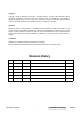
* Reader’s Response* Dear Readers: Thank you in advance for your feedback on our Service Manual, which allows continuous improvement of our products. We would appreciate your completion of the Assessment Matrix below, for return to ViewSonic Corporation. Assessment A. What do you think about the content of this Service Manual? Unit Excellent Good Fair Bad 1. Precautions and Safety Notices 2. Specification 3. Front Panel Function Control Description 4. Circuit Description 5. Adjustment Procedure 6.