ViewSonic by Premier Mounts INSTALLATION MANUAL WMK-005 UNIVERSAL PROJECTOR MOUNT Premier Mounts 3130 E. Miraloma Avenue Anaheim, CA 92806 Phone: (800) 368-9700 Fax: (800) 832-4888 www.mounts.com mounts@mounts.com IN-WMK005.
PBL-110 Projector Mount Page - 2 - Installation Manual
WMK-005 Table of Contents WARNING STATEMENTS ............................................................................................................................- 4 PARTS LIST .................................................................................................................................................- 5 INSTALLATION TOOLS ...............................................................................................................................- 5 FEATURES ...................
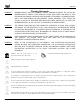
WMK-005 Warning Statements WARNING: PREMIER MOUNTS DOES NOT WARRANT AGAINST DAMAGE CAUSED BY THE USE OF ANY PREMIER MOUNTS PRODUCT FOR PURPOSES OTHER THAN THOSE FOR WHICH IT WAS DESUIGNED OR DAMAGE CAUSED BY UNAUTHORIZED ATTACHMENTS OR MODIFICATIONS, AND IS NOT RESPONSIBLE FOR ANY DAMAGES, CLAIMS, DEMANDS, SUITS ACTIONS OR CAUSES OF ACTION OF WHATEVER KIND RESULTING FROM, ARISING OUT OF OR IN ANY MANNER RELATING TO ANY SUCH USE, ATTACHMENTS OR MODIFICATIONS.
WMK-005 Parts List NOTE: This mount is shipped with all proper installation hardware and components. Make sure that none of these parts are missing and/or damaged before beginning installation. If there are parts missing and/or damaged, please stop the installation and contact Premier Mounts (800-368-9700).
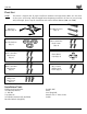
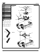
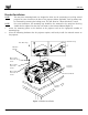
WMK-005 A B C D E F G H I J K L M Single Wooden Stud Mounts Solid Structure Mounting Points Ceiling Plate Allen Wrench Height Adjustment Screws Tension Knobs Safety Knob Security Screws Leveling Screws Universal Mounting bracket Leg Assembly Projector (not included) Tri-Lock Opening Option 1 A B C E D G F H K NOTE: The four (two-piece) leg assemblies can be used as single leg or any combination of single and dual legs together as shown in Options 1 and 2.
WMK-005 Features Congratulations on your recent purchase of your WMK-005 universal projector ceiling/ wall mount kit. This unit is designed for projectors weighing 25lbs. (13kg) or less. The mount is easy to install and is loaded with additional installation features built into the mount. These features allow you to optimize the projector’s position to the screen for the best projector performance and picture quality. • • • • • • • • • Adjustable height – 9” to 12.
WMK-005 Projector Preparation CAUTION: NOTE: 1. 2. THE PROJECTOR IS FRAGILE; HANDLE WITH CARE AT ALL TIMES. Review the projector manufacturers’ operation manual and refer to the ceiling mount installation section. Important information concerning the installation dimensions (i.e. distance from the screen to the lens of the projector, top of the lens placement to the top screen, etc.) will be found in this section.
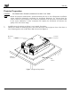
WMK-005 3. Separate the upper assembly from the projector mounting bracket by slightly loosening the two tension knurl knobs to create free play between the bracket tri-lock assembly and the upper section tri-lock assembly points (Figure 2A and Figure 2B). Loosen the security screw knurl knob far enough to allow the two parts to be rotated 180° apart and separate (Figure 2C). 4. B A Upper Assembly Tension Knobs Safety Knob Rotate 180° To unlock Tri-Lock Opening C Figure 2.
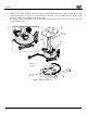
WMK-005 Bracket Installation NOTE: The two-piece mounting barrels are designed to allow for the positioning of each leg around projector air vents located on the base of the projector. Where applicable, each leg mount may be shortened by removing the locking screw. This will allow for a better bracket fit, overall. NOTE: For easier installation, the mounting legs should be first mounted to the projector. Each leg should then be adjusted so that they can mount to the Universal Mount (Figure 3). 1.
WMK-005 Leveling the Mounting Bracket CAUTION: 1. 2. 3. Secure but do not over tighten the mounting hardware. Failure to do so will result in damaging the threads in the projector. Rotate the leveling barrels to level the mounting bracket. Position the mounting bracket so that it avoids most, if not all, ventilation points (including lamp and filter access doors).
WMK-005 Securing the Upper Assembly Ceiling Plate Review your projector’s owner’s manual to determine what distance is recommended from the front of the lens to the edge of the screen for best picture ratio. However in most home theater and office ceiling mount installations this is not practical as the projector would be to low within the room.
WMK-005 Low Profile Installation OPTIONAL If your installation requires the overall height of the mount to be less that the approximate 9” shown with the standard mount assembly, you can convert the height to only 2 ½” by simply removing the adjustment channel as shown. Once the extension channel is removed, attach the upper ceiling plate to the ceiling. Once attached install the bell housing, assemble to the upper ceiling plate (Figures 6A and 6B). Removing the middle height extension.
WMK-005 Secure the ceiling plate to the ceiling structure. Wooden Stud Ceiling Structure Lag Bolts Allen Wrench Ceiling Structure Secure the bell housing with two M8 x 16mm screws and flat washers. NOTE: Do not use the star washers on a closeceiling application Re-attach the bell housing to the ceiling plate. Figure 6B.
WMK-005 Securing the Projector to the Upper Assembly 1. 2. 3. 4. Make sure the three-knurl knobs are loosened to fully expose to the “tri-lock” mounting plate in the base of the upper assembly. Carefully lift the projector and insert the mounting bracket mating special tri-lock cutout into the mating portion of the upper assembly. Once inserted rotate the projector and mounting bracket 180° and secure the rear safety knob first to prevent further rotation of the bracket in the upper assembly.
WMK-005 Final Adjustments 1. With the projector secured in the mount and power on and signal supplied to the projector you can now proceed with the final height, tilt, roll and yaw to optimize the projected image. A The height can be adjusted by slightly loosening the two 8mm height adjustment screws and raising/lowering the projector. Once the height is achieved, tighten the screws.
WMK-005 Plastic Cap Installation 1. Once all the final adjustments have been finished, install the plastic caps on the leveling barrels (Figure 9). Figure 9.
WMK-005 Troubleshooting Procedures QUESTION: ANSWER: QUESTION: ANSWER: Page - 18 - My projector mount must be set at an angle to be viewed properly on the wall, but the projector will not hold at this position. Why is this? The angle adjustments are not tight; they must be tightened. Why won’t my bracket fit my projector? There may be several mounting positions for your particular bracket. Try to line up the holes on the bracket with the mounting points on the projector.
WMK-005 Technical Specifications Figure 8 Technical Dimensions Installation Manual Page - 19 -
WMK-005 Warranty Limited Lifetime Warranty All Premier Mounts products carry a limited lifetime warranty from ship date against defects in materials and workmanship. Premier Mounts is not liable for improper installation that results in damage to mounts, adapters, display equipment or personal injury.