ViewSonic by Premier Mounts INSTALLATION INSTRUCTIONS WMK-027 Universal Short Throw Wall Mount NORTH AMERICA 3130 East Miraloma Avenue Anaheim, CA 92806 USA USA and Canada – Phone: 800-368-9700 Fax: 800-832-4888 Other Locations – Phone: (001)-714-632-7100; Fax: (001)-714-632-1044 ©Premier Mounts 2009 9530-070-353-00 EUROPE Swallow House, Shilton Industrial Estate, Shilton, Coventry, England CV79JY Phone: +44 (0) 2476 614700 Fax: +44 (0) 2476 614710
WMK-027 Table of Contents Warning Statements Parts List Installation Tools Determining the Installation Height Wood Stud Installation Solid Surface Installation Utilizing the Storage Feature Attaching the Projector Arm Throw Distance Calculation Upper Mounting Bracket Installation Extension Arm Installation Base Box Installation Cable Management Set Screw Installation
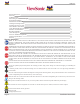
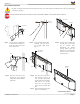
WMK-027 Parts List This mount is shipped with all proper installation hardware and components. Make sure that none of these parts are missing and/or damaged before beginning installation. If there are parts missing and/or damaged, please stop the installation and contact Premier Mounts (800) 368-9700.
WMK-027 Determining the Installation Height In order to determine the installation height and throw distance, the PDS-PLUS projector bracket must be mounted to the projector. Please refer to the PDS-PLUS Installation Instructions prior to performing the following steps. Refer to the projectors User’s Manual to determine the offset of the projector lens to the top of the screen/whiteboard. PDS-PLUS Bracket Projector Lens Step 1. Measure distance from center of lens to the top of the PDS-PLUS bracket.
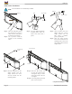
WMK-027 Wood Stud Installation Do NOT over-tighten lag bolts when attaching the mount to the wall. Improper installation may result in personal injury or damage to property. DEAD CENTER MUST BE LOCATED ON THE STUD FOR CORRECT AND SAFE INSTALLATION. Wood Stud Marking Marking (from page 4) Wood Stud Stud finder Wall Plate Step 1. Use an electronic stud finder (commercially available) to locate the center of the stud that is in the wall. Step 2.
WMK-027 Solid Surface Installation Concrete drill bits are commercially available. Hammer Marking Drill 3/8” Drill Bit Wedge Anchor Pilot Hole Step 1. Place the wall plate against the wall and use a level to make sure the wall plate is level from top to bottom. Step 2. Use a pencil to mark the location of the mounting holes. Seated Wedge Anchor Step 3. Use a 3/8” drill bit to drill the mounting holes where the marks were made with a pencil. Step 4.
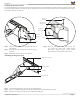
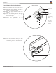
WMK-027 Utilizing the Storage Feature The storage feature may be used to store electronic components. There is an accessible door on each side of the storage enclosure. It may be securely held shut with the use of four (4) M5 x 12mm security head screws. It may be easiest to pre-wire all cables down the arm (or extension) at this time (see Page 11). Security Wrench M5 x 12mm Security Screw Electronic Components Electronic Components Door Door Step 1.
WMK-027 MAKE SURE THE PROJECTOR ARM IS FULLY SEATED BEFORE RELEASING THE UNIT. Lock Mounting Point M5 x 12mm Security Head Screw Screwdriver/Security Wrench Step 4. Locate the two (2) lock mounting points on the projector arm. These two points will be aligned with the lock mounting points on the wall plate. Step 5. Using a security wrench, insert and tighten two (2) M5 x 12mm security head screws. DO NOT OVERTIGHTEN THE SCREWS.
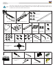
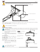
WMK-027 Upper Mounting Bracket Installation Step 1. Insert the inner slide plate into the projector arm. Step 2. Determine which adjustment slot will be best for the projector placement. Step 3. Raise the upper mounting bracket into position. Step 4. Align the mounting holes of the upper projector plate with the mounting holes of the inner slide plate. Step 5. Secure and finger-tighten two (2) M6 x 12mm security head screws.
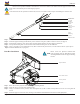
WMK-027 Extension Arm Installation (Optional) Please see the Operator’s Manual to determine the correct throw distance (the distance from the projector to the screen) must be determined prior to mounting the projector. If the extension arm was purchased at a later date, the end cover must be removed prior to installing the extension arm. WMK-027 1/4” Flat Washers 1/4” Nylon Spacer M6 x 12 Security Screw Security Wrench Upper Mounting Bracket Extension Arm Step 1. Step 2. Step 3. Step 4. Step 5. Step 6.
WMK-027 Cable Management WMK-027 Electronic Components Electronic Components WMK-027 Cables Electronic Components Cable Opening Cable Opening Projector Hook-Ups Cables Cable Opening Projector Hook-Ups Step 1. The cable access holes are located at the end of the short throw mount and on the wall plate. Step 2. Route the cables through one end of the WMK-027 and out the other end.
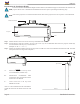
WMK-027 Technical Specifications All measurements are in inches(mm).
WMK-027 Warranty PREMIER MOUNTS LIMITED LIFETIME WARRANTY What and Who is Covered by this Limited Warranty and for How Long Premier Mounts warrants this product to be free from defects in material and workmanship for the lifetime of the original owner of this product. The limited warranty is valid only for the original purchaser of the product. What Premier Mounts Will Do At the sole option of Premier Mounts, Premier Mounts will repair or replace any product or product part that is defective.