Installation Guide Viking Range, LLC 111 Front Street Greenwood, Mississippi 38930 USA (662) 455-1200 For product information, call 1-888-(845-4641) or visit the Viking Web site at vikingrange.
Table of Contents IMPORTANT — Please Read and Follow Warnings & Important Information ____________________________________________________________________3 Bottom-Freezer Dimensions and Specifications (36”) __________________________________________________________6 Cutout Dimensions (36”) ____________________________________________________________________8 Anti-Tip Dimensions (36”) ___________________________________________________________________9 Overlay Dimensions (36”) _____________________________
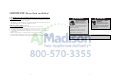
IMPORTANT—Please Read and Follow! A GFI shall be used if required by NFPA-70 (National Electric Code), federal/state/local laws, or local ordinances. • The required use of a GFI is normally related to the location of a receptacle with respect to any significant sources of water or moisture. • Viking Range, LLC will NOT warranty any problems resulting from GFI outlets which are not installed properly or do not meet the requirements below.
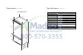
Dimensions Specifications (Bottom-Freezer) 36” Bottom-Freezer (Bottom-Freezer) 36” Bottom-Freezer Description Overall width Overall height (from bottom) Overall depth (from rear) 3 (88 5” .9 c m 3-1 (8.9 /2” cm ) Cutout width Cutout height Cutout depth Electrical requirements 3 (91 6” .4 c m ) ) Maximum amp usage Inlet water requirements ies var ) 51 (13 -7/8” 1 .
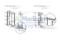
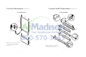
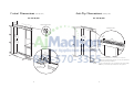
Cutout Dimensions Anti-Tip Dimensions (Bottom-Freezer) 36” Bottom-Freezer 24” ) cm (61.0 See an ti-tip b oard in (Bottom-Freezer) 36” Bottom-Freezer Electric Outlet Location stallati on 6” (15.2 cm) Anti-Tip Location 9” (22.9 cm) 9” (22.9 cm) 79 29” (73.7 c m) 8 (20 0-1/2 84 4.6 (213 -1/16” .5 anti- cm) m t a op ip boa x. r g he d & ight (3.8 c anti- ttom of tip b oard penin rd g he & ight enin ” 1-1/2m) (201 -3/8” .6 to bo cm) min . 82 (210 -7/8” .
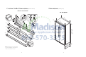
Overlay Dimensions (Bottom-Freezer) Custom Grille Dimensions 36” Custom Panels (Bottom-Freezer) 36” Custom Grille 1 ” 3/4 ) s diu Ra ) 35 cm 4” m 1/ (.16.42 c - (89 1/4” .5 c m) 3” m) 7 (1.2 2 (7.6 (10 1/64 .59 ” 5-1 3” m) 2c (7.6 Reverse dimensions for other end. /4” 3-3 cm) (1.9/4” 0c m) /8” 3-5 cm) 0 1 (1.2/2” 7c m) (9.2 3 (86 4” .36 c 2-1 m) 32 -1/ 4” Note: Inset shown upside down. (81 to n .9 c ot m ) ch ” 3/4 ) 1/2 - (1.2 ” 7c m) 2 (9.5 -1 (86 5/1 .
Custom Grille Dimensions Dimensions (Bottom-Freezer) (Side-By-Side) Dual 36” Custom Grille 42” Side-By-Side 4-1 (11 1/64 1 (1.2/2” 7c m) s d iu Ra ) 4” 42 cm / 1 (.16. .27 ” cm ) ” 1/2cm) 7 (1 .2 1 (.3 1/ 8” cm ) Reverse dimensions for other end. / 4” 3 -3 m ) 3 (1.9/4” 0c (9 .5 m) 2c - 3/ 4 (1 .9 ” 0c m) R 3/32” (0.09 cm) 2c (1.90 cm) (0.38 cm) (1.90 cm) Grille support (7.3 /8” 0c m) ” 1 (2.5 ” 4c m) 78 0c m) 2 / 8” 3 -1 c m ) 3 (7.9 (1 7 70” 7 .
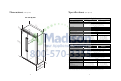
Dimensions Specifications (Side-By-Side) 48” Side-By-Side 42” Side-By-Side Description Overall width Overall height (from bottom) Overall depth (from rear) 4 (11 7” 9.4 c 3-1 (8.9 /2” cm ) 751 (19 5/16 2 ” .9 c m) Cutout width Cutout height Cutout depth Electrical requirements m) 4 (12 8” 1.
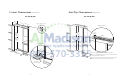
Cutout Dimensions Anti-Tip Dimensions (Side-By-Side) 42” Side-By-Side 42” Side-By-Side 24” ) cm (61.0 See an ti-tip b oard in Electric Outlet Location stallati on 6” (15.2 9” (22.9 Anti-Tip Location cm) cm) 9” (22.9 cm) 79 (201 -3/8” .6 to bo cm) min . 82 (210 -7/8” .5 anti- cm) min tip b . oa o 35” (88.9 c m) 8 (204 0-1/2” .6 to bo cm) max . ttom a 84-1 / (213 .5 16” anti- cm) m tip b a op oa x. r g he d & ight ” 1-1/2m) (3.
Cutout Dimensions Anti-Tip Dimensions (Side-By-Side) (Side-By-Side) 48” Side-By-Side 48” Side-By-Side 24” ) cm (61.0 See an ti-tip b oard in Electric Outlet Location stallati on 6” (15.2 9” (22.9 cm) Anti-Tip Location cm) 9” (22.9 cm) 82 (210 –7/8” .5 anti- cm) min tip b . oa o 79 (201 -3/8” .6 cm )m to 84 (213 –1/16” .5 anti- cm) m t a op ip boa x. enin r g he d & ight ” 1-1/2m) bo in. anti- ttom of tip b oard penin rd g he & ight (3.8 c 41” (104.1 8 (20 0-1/2 4.
Overlay Dimensions 42” Custom Panels ” 3/ 4 ) (1.9 cm 18 -3 (46 /16 .2 c ” m) ” 3/4cm) (1.9 cm (1.9 18 -3 ” 3/4 ) -13 (46 /16 .2 c ” m) cm (1.9 (57 /16 .9 c ” m) ” 3/4 ) - -1 (47 1/16 .5 c ” m) ” 3/4cm) (1.9 ” 3/4cm) -5 (71 /16 .9 c ” m) m c (1.9 -1 (80 5/8” .3 c m) 48” Custom Panels with Dispenser 18 28 22 31 -1 (47 1/16 .5 c ” m) ” 3/4cm) (1.9 28 -5/ (57 3/16 .9 c ” m) (71 16 .9 c ” m) 31 - (80 5/8” .3 c m) 10 -1 -1 (27 1/16 .1 c ” m) (27 1/16 .
Custom Grille Dimensions Custom Grille Dimensions (Side-By-Side) 42” Custom Grille 48” Custom Grille 1 (1.2/2” 7c m) 1 cm ) ” 2c m) (. 3 (1.9/4” 0c m) m) 3 -1 cm ) (1.9/4” 0c m) (9.5 2 1 /4 ” 3 -3 m ) 3 /4 (1.9 ” 0c m) (1.2/2” 7c m) 3/4 (1.9 ” 0c m) 39 (10 15/1 1.4 6” 4 cm ) 3c 1/2 (1.2 ” 7c m) 41 cm ) ove 32 -3 /8” 3-5 cm) 0 (9.2 2 (9.5 45 (7.9 3 ” 7/8cm) Op tio nal (3. 49 ” cm ) /8 ” ) cm m) ” 39 c .94 -1 (5. /8 2 -1 /8 ” s iu ad R (.
Cabinet Information Cabinet Information Custom panel models, (with 3/4” [1.9 cm], thick panels and custom handles locally supplied), fit flush in 25” (63.5 cm) deep (countertop depth) cabinet openings with no protrusion into room except custom handles Custom panel models can be installed in standard 24” (61.0 cm) deep openings. However, the door faces and top ventilation grille will protrude 3/4” (1.9 cm) into the room. This is ideal for alignment with full overlay cabinet doors.
Custom Side Panel Dimensions Custom Panel General Information Custom finishing options Z-Bracket 1” (2.5 cm) 1/4” (0.6 cm) 4” -3/cm) 1 2 (55 • Panel thickness must not exceed 1” (2.5 cm) on hinge side. Thicker panels will interfere with door swing and clearance. • Door panels should be installed after the refrigerator has been plugged in for at least 24 hours. • All installations must allow for the refrigerator and freezer door to open a minimum of 90˚.
Ice and Water Dispenser Bezel Removal 5 (if required cont.) 6 Custom Door Panel Installation 2 1 Remove handle side cabinet screws and trim with a phillips screwdriver. Remove mounting support. 7 8 3 x2 x13 x13 Remove 2 additional screws under top section of bezel. (Refrigerator or Freezer) x2 Remove all screws from handle side door trim. Remove two screws from top and bottom door trim. Remove handle side door trim. 3 4 2-1/16” (5.2 cm) 1-11/16” (4.3 cm) 2-13/16” (7.
Custom Door Panel Installation 7 Custom Freezer Door Panel Installation (Bottom-Freezer Only cont.) (Refrigerator or Freezer cont.) 2 1 8 x2 x13 x2 Reinstall handle side door trim and door trim screws. Slide custom wood panel to the hinge side, ensuring “Z” bracket engages the door bracket. x16 Open freezer door. Remove door trim screws and door trim with a phillips screwdriver. Remove bracket. 3 9 4 2-1/16” 2-1/16” (5.2 cm) (5.2 cm) 1-11/16” x13 1-11/16” (4.3 cm) (4.
Ice and Water Dispenser Bezel Installation (if required) 2 1 Install custom wood panels per product’s installation instructions. Ice and Water Dispenser Bezel Installation (if required cont.) 7 Locate opening in door and position bezel. Note: Graphics on bezel will be on top end, tilt slightly forward to allow water tube clearance. 3 Install two screws in lower part of bezel but DO NOT tighten all the way. 5 6 For a left hinge door, cut 5/8” x 2-3/4” in lower left corner.
Bottom-Freezer Custom Panel Hinge Cutout (if required) 3 4 3 2 (.2 /3 4 2” cm ) 1 Custom Grille Installation (cont.) ” 6 ) /1 3 cm -1 0 1 4.6 ( 3 5/ (1.6 8” cm ) 2 1 3 (7.6 ” 2c m ) For a left hinge door, cut 5/8” x 3” in lower left corner. Note: Steps show panel upside down and notched for left hinge application. Mirror dimensions for right hinge door. 1 3 5/ Pull air grille assembly forward. Measure and cut 2-1/16” diagonal in lower left corner.
General Information General Information Area Requirements Water Supply Requirements A 115 volt, 60-Hz, 15 amp, fused, electrical supply is required. It is required that a separate circuit serving only this appliance be provided. This appliance is equipped with a power supply cord having a 3-prong grounding plug. To minimize possible shock hazard, the cord must be plugged into a mating 3-prong, grounding-type wall receptacle. DO NOT use an extension cord.
Installation General Information 1 2 Tip Over Hazard • Most of the unit’s weight is at the top. Extra care is needed when moving the unit to prevent tipping. • DO NOT remove protective film until unit is in operating position. • All four leveling legs must make contact with the floor to support and stabilize the full weight. Appliance is top heavy and tips easily when not completely installed. Keep doors closed until appliance is completely installed and secured per installation instructions.
Hinge Adjustment Installation (cont.) 6 5 Front of unit 10b 10a 2 2 3” 1 1 Remove four side screws and remove unit top. 3 Loosen the four hinge screws. Adjust door. Retighten four hinge screws. 8a 7 Place unit within 3” of being flush with cabinets. Note: To avoid cabinet damage, place cardboard between cabinets and unit. When moving unit, DO NOT crimp, kink or crush water supply line. Carefully move unit until semi flush with cabinet (depending on unit).
Hinge Adjustment (cont.) Door Stop Adjustment (Side-by-Side) 20 16 15 21 1 1 120˚ Screw Wall 110˚ 90˚ 3 2x4 Refrigerator Open refrigerator door so door stop and shoulder screw are accessible. Note: Shoulder screw should be in 110˚ door opening position. Attach positive secure self-tapping bolts to 2 x 4 using a 22” extension. Lift unit off rollers to desired height and level unit using a 5/16” head wrench. Note: DO NOT use an electric device. Overtightening can cause damage.
Water Filter Installation (Side-by-Side with Dispenser) 24 Water Filter System Specification and Performance Data Sheet 25 This system has been tested according to NSF/ANSI 42/53 for reduction of the substances listed below. The concentration of the indicated substances in water entering the system was reduced to a concentration of less than or equal to the permissible limit for water leaving the system, as specified in NSF/ANSI 42/53.
Final Installation Performance Checklist 29 28 Replace top air grille. Using an 8” magnetic nut driver, replace the two 1/4” screws. 30 31 Replace the center grille louver. Open door. The display should flash. 32 □ Verify cabinet size. □ Align/square door(s). □ Verify electrical supply and water supply (if applicable). □ Verify drain pan is properly installed and there are no leaks on water connection. □ Install anti-tip device(s) and verify unit is secure. □ Install kickplate.
Verify Operations Service & Registration Control Panels If service is required, call your dealer or authorized service agency. The name of the authorized service agency can be obtained from the dealer or distributor in your area.
Notes Notes ________________________________________________________________________________________________________________________________________________________ ________________________________________________________________________________________________________________________________________________________ ________________________________________________________________________________________________________________________________________________________ _____________________________________