Installation GUIDE 5 SERIES Side-by-Side Refrigerator/Freezer VCSB5423 / VCSB5483 / FDSB5423 / FDSB5483 CVCSB5423 / CVCSB5483 / FDSB5423 / CFDSB5483
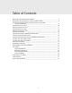
Table of Contents Warnings and Important Information _________________________________ 3 Dimensions & Specifications (Professional 42” & 48”) _____________________ 6 Dimensions & Specifications (Professional 42” & 48” with flush mount trim) _____________________________________________ 8 Cutout Dimensions (42”) __________________________________________ 10 Anti-Tip Dimensions (42”) _________________________________________ 11 Cutout Dimensions (48”) __________________________________________ 12 Anti-Tip Dim
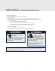
IMPORTANT – Please Read and Follow! • Make sure that incoming voltage is the same as unit rating. An electric rating plate specifying voltage, frequency, wattage, amperage, and phase is attached to the product. • To reduce the risk of fire, electrical shock, or injury to persons, installation work and electrical wiring must be done by a qualified technician in accordance with all applicable codes and standards, including fire-rated construction.
IMPORTANT – Please Read and Follow! A GFI shall be used if required by NFPA-70 (National Electric Code), federal/state/local laws, or local ordinances. • The required use of a GFI is normally related to the location of a receptacle with respect to any significant sources of water or moisture. • Viking Range, LLC will NOT warranty any problems resulting from GFI outlets which are not installed properly or do not meet the requirements below.
IMPORTANT – Please Read and Follow! It is your responsibility to: • comply with installation specifications and dimensions. • properly install unit. • remove any moldings or decorative panels that prevent the unit from being serviced. • make sure that you have these materials (not provided with your unit), which are necessary for proper installation: • 1/4” (6 mm) copper tubing with shutoff valve • 6– #8 x 3” (7.
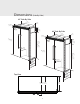
Dimensions (Side-By-Side) 42” Side-By Side 41” (104.1 3–19/ 3 (9.1 cm2” ) /2” 1–1cm) cm) (3.8 42” (106.7 cm) 9–5 / (23. 32” 3 cm ) 48” Side-By Side 47” (119.4 3–19/ 3 (9.1 cm2” ) /2” 1–1cm) cm) (3.8 48” (121.9 cm) 75–1 (192 5/16” .9 cm ) 9–5 82 / (23. 32” 3 cm ) (21 –3/4” 0.2 min cm) . 84–to (21 1/16” 3.5 ma cm) x. 16” 29-3/ cm) (74.1 75–1 (192 5/16” .9 cm ) 8” –7/ ) 23 .6 cm 0 (6 8” -5/ ) 24 .6 cm 2 6 ( 4” -1/ ) 26 .7 cm 82 (21 –3/4” 0.2 min cm) . 84–to (21 1/16” 3.
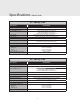
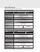
Specifications (Side-By-Side) 42” Side-By-Side Description VCSB/CVCSB Overall width 42” (106.7 cm) Overall height (from bottom) Overall depth from rear Cutout width Cutout height 82-3/4” (210.2 cm) min. to 84-1/16” (213.5 cm) max. To front edge of side trim: 23-3/4 (60.3 cm) To front of top grille: 26-1/4” (66.7cm) To front of handle endcap: 29-3/16” (74.1 cm) 41-5/8” (105.7 cm) min. to 41-3/4” (106 cm) max. 82-7/8” (210.5 cm) min. to 84-1/16” (213.5 cm) max. Standard Cutout depth 24” (61.0 cm) min.
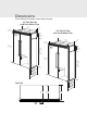
Dimensions (Flush Mount Trim and Custom Door Overlay) 42” Side-By Side with Flush Mount Trim 41” (104.1 3–19/ 3 (9.1 cm2” ) /2” 1–1cm) cm) (3.8 42” (106.7 cm) 48” Side-By Side with Flush Mount Trim 9–5 / (23. 32” 3 cm ) 47” (119.4 3–19/ 3 (9.1 cm2” ) /2” 1–1cm) cm) (3.8 48” (121.9 cm) 75–1 (192 5/16” .9 cm ) 9–5 82 / (23. 32” 3 cm ) (21 –3/4” 0.2 min cm) . 84–to (21 1/16” 3.5 ma cm) x. 16” 29-3/ cm) (74.1 75–1 (192 5/16” .9 cm ) 8” -7/ ) 23.
Specifications (Flush Mount Trim and Custom Door Overlay) 42” Side-By-Side Flush Mount Trim and Custom Door Overlay Description VCSB/CVCSB Flush Mount FDSB/CFDSB Overall width Overall height (from bottom) Overall depth from rear 42” (106.7 cm) 82-3/4” (210.2 cm) min. to 84-1/16” (213.5 cm) max. Cutout width To front edge of side trim: 25-1/2" (64.8) To front of top grille: 26-1/4” (66.7 cm) To front of handle endcap: 29-3/16” (74.1 cm) 42” (106.7 cm) Cutout height 82-7/8” (210.5 cm) min.
Cutout Dimensions unt o ard M Stand 24” ) (61.0 42” Side-By-Side cm t Moun Flush3/8” 26- cm) (67.0 See An ti-Tip b oard in Electric Outlet Location stallatio n 6” (15.2 9” (22.9 cm) cm) 9” (22.9 cm) 82 (210 –7/8” .5 anti- cm) m in tip open board . & ing h eigh t 84 (213 –1/16” .5 anti- cm) m tip b ax. ope ning oard & heig ht 73-3 (186.4/8” cm) Water Line Entry Area 42 ” (1 Flus 06.7 cm h Mo ) unt only 41– (105 5/8” .7 cm ) 7–5/ (19.4 8” 6 –3 cm) (17.1/4” (1.6 cm) cm) 3” (7.
Anti-Tip Dimensions 42” Side-By-Side Anti-Tip Location One 2”x 4” Mounting Board 3” (7.6 cm) x 3-1/2” (8.9 cm) 1.5” ) m (3.8 c 35” (88.9 c m ) 79–3 (201 .6 3–1/2 /8” (8.9 c ” m) to bo cm) min . anti- ttom of tip b oard 8 (204 0–1/2” .6 to bocm) max . anti- ttom of tip b oard NOTE: If unit is installed deeper than 24” (61.0 cm), then shim behind the mounting board by the difference. Bottom of anti-tip board is 3–7/8” (9.8 cm) below opening height.
Cutout Dimensions 48” Side-By-Side ount ard M Stand 24” ) (61.0 cm t Moun Flush3/8” 26 m) (67.0 c See An ti-Tip b oard in Electric Outlet Location stallati on 6” (15.2 9” (22.9 cm) cm) 9” (22.9 cm) 82 (210 –7/8” .5 anti- cm) m in tip open board . & ing h eigh t 84 (213 –1/16” .5 anti- cm) m tip b ax. ope ning oard & heig ht 73-3 (186.4/8” cm) Water Line Entry Area 48 ” (1 Flus 21.9 cm h Mo ) unt only 47– 7–5/ 5/8” (121 47–5 .0 /8 (121 47– to cm) min” . .
Anti-Tip Dimensions 48” Side-By-Side Anti-Tip Location One 2”x 4” Mounting Board 1-1/2” (3.8 cm) x 3-1/2” (8.9 cm) ” 1-1/2m) (3.8 c 79 (201 –3/8” .6 to bo cm) min . 41” (104.1 anti- ttom of tip b oard cm) 3– 1/2 (8.9 c ” m) 8 (204 0–1/2” .6 to bo cm) max . anti- ttom of tip b oard NOTE: If unit is installed deeper than 24” (61.0 cm), then shim behind the mounting board by the difference. Bottom of anti-tip board is 3–7/8” (9.8 cm) below opening height.
Cabinet Information For installation in 24" (61.0 cm) deep cabinets, the door face protrudes 2-3/4” (7.0 cm) from the cabinet face. The handle protrudes an additional 2-15/16” (7.5 cm) into the room. Standard Mount Installation 1/4” (0.6 cm) 42” (106.7 cm) 48” (121.9 cm) Finished Wall 24” (61.0 cm) 41” (104.1 cm) 47” (119.4 cm) 24-3/4” (62.9 cm) 23-3/4” (60.3 cm) 26-1/4” (66.7 cm) Standard Side trim Face of stainless steel door 2-3/8” (6.0 cm) 27/32” (0.
HeadlineInformation (with Flush Mount Trim) Cabinet Flush Mount Installation with Standard Cabinets 1/8” (0.3 cm) Offset in Finished Wall Finished Wall 1-5/8” (4.1 cm) 23-7/8” (60.6 cm) 24” (61.0 cm) 26-3/8” (67.0 cm) 24-5/8” (62.5 cm) 24-3/4” (62.9 cm) 26-1/4” (66.7 cm) Face of cabinet frame Flush Side trim 3/4” (.6 cm) Face of door/drawer * *The face of the door skin needs to be on the same plane, flush with the cabinets.
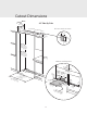
Custom Side Panel Dimensions 3/16” (0.5 cm) Back filler panel /8” 4-5 cm) 2 .5 (62 3/4” (1.9 cm) End panel 6”cm) .2 (15 5/32” (0.4 cm) 8” -5/ ) 24.5 cm (62 (2182-7 0.5 /8 cm ” )m 8 in. (21 4-1to 3.5 /1 cm 6” )m ax .* (2182-7 0.5 /8 cm ” )m in. (21 84-1to 3.5 /1 cm 6” )m ax .* * Depending on how high leveling feet are raised, and cabinet enclosure height.
Custom Side Panel Dimensions (with Flush Mount Trim) Z-Bracket 1” (2.5 cm) 8” -7/ ) 23.6 cm 3/4” 1/4” (0.6 cm) (1.9 cm) End panel (60 8” -7/ ) 23.6 cm (60 (2182-7 0.5 /8 cm ” )m in. (21 84-1to 3.5 /1 cm 6” )m ax .* (2182-7 0.5 /8 cm ” )m in. (21 84-1to 3.5 /1 cm 6” )m ax .* * Depending on how high leveling feet are raised, and cabinet enclosure height. 8” -3/ ) 26.0 cm (67 Optional kickplate Notch dimensions determined by cabinets 8” -3/ ) 26.0 cm (67 Top View - Assembled 1/8” (0.
Custom Door Panel Dimensions Freezer Refrigerator 42” Side-By-Side ” 3/4cm) (1.9 Maximum Panel WT 42" 48" 30lbs (13.6 kg) 30lbs (13.6 kg) 38lbs (17.2 kg) 48lbs (21.8 kg) 18 -3 (46 /16 .2 c ” m) ” 3/4cm) (1.9 22 -1 (57 3/16 .9 c ” m) 48” Side-By-Side ” 3/4cm) (1.9 18 -1 (47 1/16 .5 c ” m) ” 3/4cm) (1.9 28 -5 (71 /16 .9 c ” m) 75 (19 -1/2 1.8 ” cm ) 75 (19 -1/2 1.8 ” cm ) Note: Panel overlays must be dry, solid, straight one piece panels.
Custom Door Panel Installation 2 1 x2 x13 x13 Remove handle side cabinet screws and trim with a Phillips screwdriver. x2 Remove all screws from handle side door trim. Remove two screws from top and bottom door trim. Remove handle side door trim. 4 3 2-1/16” (5.2 cm) 1-11/16” (4.3 cm) 2-13/16” (7.1 cm) Bottom-mount 12-1/16” (30.6 cm) All Refrigerator/ Freezer/ Side-by-side 2-1/8” (5.4 cm) Back of panel “Z” bracket Remove bracket.
Custom Door Panel Installation 8 7 x2 x13 x2 Slide custom wood panel to the hinge side, ensuring “Z” bracket engages the door bracket. Reinstall handle side door trim and door trim screws. 9 x13 Reinstall cabinet trim and screws.
48” Custom Panels HeadlineInformation General Area Requirements A 115 volt, 60-Hz, 15 amp, fused, electrical supply is required. It is required that a separate circuit serving only this appliance be provided. This appliance is equipped with a power supply cord having a 3-prong grounding plug. To minimize possible shock hazard, the cord must be plugged into a mating 3-prong, groundingtype wall receptacle. DO NOT use an extension cord.
HeadlineInformation General • DO NOT use plastic water lines from the household plumbing to the water inlet valve connection on the refrigeration unit. WARNING To avoid serious illness or death, DO NOT use unit where water is microbiologically unsafe or of unknown quality, without adequate disinfection before or after the system. Systems certified for cyst reduction may be used on disinfected water that may contain filterable cysts.
HeadlineInformation General Area Requirements Tip Over Hazard • Most of the unit’s weight is at the top. Extra care is needed when moving the unit to prevent tipping. Appliance is top heavy and tips easily when not completely installed. Keep doors closed until appliance is completely installed and secured per installation instructions. Use two or more people to move and install appliance. Failure to do so can result in death or serious injury.
Headline Flush Mount Side Trim Installation (Sold Separately) Note: If the unit is to be installed flush with the cabinets, the flush mount side trim must be installed first. If not, skip to “Installation”. Step 3 - Align the top of the flush mount side trim with the top of the unit's machine compartment. Using the screws included in the hardware kit, attach the side trim to the unit, only using the holes visible through the side trim. Note: DO NOT use the screw holes in the machine compartment.
Installation Headline Hinge Adjustment 5 6 Front of unit 2 2 1 1 Remove four side screws and remove unit top. 3 Loosen the four hinge screws. Adjust door. Retighten four hinge screws. Anti-Tip Installation 7 8a 1 Wall 2 2x4 Refrigerator Replace unit top. Replace four side screws. Attach one 2 x 4 to wall stud (refer to dimensions page for exact location). 8b 9 Wall 2x4 Refrigerator If needed, depending on cabinet and depth, attach second 2 x 4 to first 2 x 4.
Installation Headline 10b 10a 3” Place unit within 3” (7.6 cm) of being flush with cabinets. Note: To avoid cabinet damage, place cardboard between cabinets and unit. When moving unit, DO NOT crimp, kink or crush water supply line. Carefully move unit until semi flush with cabinet (depending on unit). 12 11 Pull supply tubing forward under unit. Note: DO NOT use plastic water lines. Flush water line by running two quarts of water into a bucket. Turn water off.
Installation Headline 16 15 Screw Wall 2x4 Refrigerator Lift unit off rollers to desired height and level unit using a 5/16” head wrench. NOTE: DO NOT use an electric device. Overtightening can cause damage. Insert mounting screws into 2x4 attached to wall stud 17 Make sure evaporator pan is in correct location. Kickplate Installation 18 19 1 1 2 3 2 Align holes on both ends of louvered panels and insert screws.
Headline Door Stop Adjustment 20 21 1 1 90˚ 110˚ 120˚ 3 2 2 Open refrigerator door so door stop and shoulder screw are accessible. Note: Shoulder screw should be in 110º door opening position. Remove shoulder screw and place in 90º or 120º position.
Final Installation Headline 23 22 Replace top air grille. Using an 8” (20.3 cm) magnetic nut driver, replace the two 1/4” (0.6 cm) screws. 25 24 Replace the center grille louver. Open door. The display should flash. 26 Press “ACTIVATE CONTROLS” pad and close door. Note: There is a 6 minute delay before the unit starts.
Headline Performance Checklist —Verify cabinet size. —Verify electrical supply and water supply (if applicable). —Install anti-tip device(s) and verify unit is secure. —Position unit in cutout, level at desired height and secure unit. —Plug-in unit and verify operation. —Connect water supply (if applicable). • Verify icemaker fill tube is properly inserted. • Verify icemaker bail arm is down. • Verify dispenser operation (if applicable). —Align/square door(s).
Verify Operations Headline Control Panel Side-by-Side FREEZER CF MAX FRZ MAX REF FAST COOL SAB SHOW 1. 2. 3. 4. 5. REFRIGERATOR DOOR OPEN POWER HIGH TEMP ACTIVATE CONTROLS FRZ TEMP REF TEMP HIGHER LOWER FAST COOL MAX REF MAX FRZ ALARM OFF DISPLAY OFF Press “ACTIVATE CONTROLS” pad. Verify unit is not in Sabbath Mode. If in Sabbath Mode: A. The Sabbath Mode will disable the interior lights, display (except SAB indicator, temperature and compartment indicator) and alarm.
Headline Service & Registration If service is required, call your authorized service agency. Have the following information readily available. • Model number • Serial number • Date purchased • Name of dealer from whom purchased Clearly describe the problem that you are having.