
Specifications

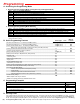

Due to the dynamic nature of the product design, the information contained in this document is subject to change without notice. Viking Electronics, and its affiliates and/or
subsidiaries assume no responsibility for errors and omissions contained in this information. Revisions of this document or new editions of it may be issued to incorporate
such changes.
Fax Back Doc 168 ZFXXXXXX Rev 3Printed in the U.S.A.
P
P
r
r
o
o
d
d
u
u
c
c
t
t
S
S
u
u
p
p
p
p
o
o
r
r
t
t
L
L
i
i
n
n
e
e
.
.
.
.
.
.
7
7
1
1
5
5
.
.
3
3
8
8
6
6
.
.
8
8
6
6
6
6
6
6
F
F
a
a
x
x
B
B
a
a
c
c
k
k
L
L
i
i
n
n
e
e
.
.
.
.
.
.
7
7
1
1
5
5
.
.
3
3
8
8
6
6
.
.
4
4
3
3
4
4
5
5
(8)
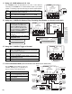
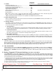
6. Auxiliary Contacts
The auxiliary contacts are a separate set of contacts that can be programmed (see Programming section B) to activate in dif-
ferent patterns when doorbox 1 or doorbox 2 is off hook. A momentary activation, a continuous activation while the doorbox is
in use, and a ring cadence pattern are available.
If an auxiliary contact activation time is programmed (two digits 00-10 followed by #03), when either doorbox is activated, the
auxiliary contacts will activate for the programmed time (.5 - 10 seconds). This is ideal for operating a doorbell or chime.
a. Timed Activation
If the auxiliary contact is programmed to continuously activate (11 followed by #03), while either doorbox is ringing or in use,
the auxiliary contacts will latch. This is ideal for controlling cameras, lights, etc.
b. Continuous Activation
If the auxiliary contact is programmed to custom ring cadence (“12 #03”) when doorbox 1 is activated, a repeating 1 second
on and 3 seconds off contact pattern is generated. If doorbox 2 is activated, a repeating double burst contact pattern is gen-
erated with 3 seconds off between patterns. Note: Ring cadence activation is not compatible with the Analog PABX/KSU
Station mode.
c. Ring Cadence Activation
Activate doorstrike relay 1 or 2 .............................................................
Continuously activate doorstrike relay 1 or 2 ........................................
Continuously de-activate doorstrike relay 1 or 2 ..................................
Activate opposite doorstrike relay ........................................................
Toggle relay from last position ..............................................................
Answer or disconnect a doorbox call ....................................................
Monitor doorbox 1 ................................................................................
Monitor doorbox 2 ................................................................................
*
Pulse Dial/Flash Commands
✱✱ Pulse dial 3 or hook flash 3 times
✱ 1
✱ 0
✱ 2
✱ #
# Pulse dial 2 or hook flash 2 times
# 1
# 2
Touch Tone
Commands
4. Features
Note: When on the C.O. line, if a Touch Tone other than # is entered, any additional Touch Tones in that dial string will be
ignored. To regain control of the C-1000B, the phone must be momentarily placed on-hook.
* Note: Pulse dialing and flash commands are not compatible in the “Multiple Relay Activation” mode.
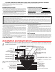
5. Keyless Entry/Postal Lock
When a momentary postal lock contact closure is made across terminals 6 & 7 (see Installation section D), the doorstrike 1 con-
tact will activate for the programmed time.
The first ringing line will ring to the “LINE OUT TO PHONES“ terminals 4 & 5 on the C-1000B. On outbound calls, the C-1000B will
default to the primary line (line connected to the “PHONE LINE INPUT“ terminals 2 & 3). To access the lines connected to “DOOR-
BOX 1“ terminals or “DOORBOX 2“ terminals, simply dial Touch Tones “#1” or “#2” respectively. Note: DIP switch 3 must be in the
OFF position.
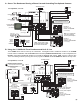
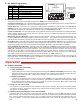
B. Paging Controller
C. Line Concentrator
In this mode a paging system that provides talk battery (Viking PA-2A or CPA-7B) can be connected to one of the doorbox ports.
When the person on the phone wants to make a page, they can enter “#” and a 1 or 2 depending on which port the paging amplifi-
er is on. After the announcement is made, if a call was in progress, another “#” will return them to the phone conversation. If a door-
box is used in this mode, enter “✱✱” to activate the relay contact followed by a “#” to return to a caller on hold.
The C-1000B allows two CCTV video cameras to be concentrated down to one video signal, by switching to the camera at the
zone/entry point being used. When the C-1000B detects doorbox ringing or when a doorbox is monitored it will connect that camera’s
video feed to the video output. This happens in a first come, first serve manner. When both doorboxes are inactive (idle) the C-1000B
can be programmed to do one of four operations:
1. Disconnect all cameras so there is no video output. This mode is very convenient when used in combination with a switching video RF modulator
(Radio Shack part # 15-1214 or equivalent), which automatically switches the video source in when a video signal is present. A home TV’s broad-
cast/satellite program will be automatically interrupted to show video feed of the arriving guest (see Installation section A).
2. Connect video feed from camera 1.
3. Remain connected to the camera near the last doorbox activated and continue feeding video from it until the other doorbox is activated.
4. Sequence video from both cameras connected, rotating every 4 seconds.
D. Doorbox Triggered CCTV Camera Switching (CCTV Video Control Mode)