
Specifications
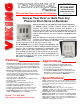

DOOR ENTRY / CCTV VIDEO
/ PAGING CONTROLLER
VIKING
©
MODEL C-1000B
P
W
R
1
3
.8
V
A
C
D
O
O
R
S
T
R
IK
E
1
D
O
O
R
S
T
R
IK
E
2
D
O
O
R
B
O
X
2
D
O
O
R
B
O
X
P
W
R
O
U
T
P
U
T
D
O
O
R
B
O
X
1
123456789
10 11 12 13
14 15 16 17 18 19
EARTH
GND
PHONE LINE
INPUT
LINE OUT
TO PHONES
KEYLESS CONTACT
CLOSURE INPUT
VIKING
ELECTRONICS
HUDSON, WI 54016
EARTH
GND
C.O. LINE
INPUT
OUT TO
PHONES
KEYLESS
C.C. INPUT
DOOR
BOX 1
DOORBOX
13VAC PWR
DOOR
BOX 2
N.O. COM N.C.
DOOR STRIKE 1
SIG GND
VIDEO 1 IN
SIG GND
VIDEO 2 IN
SIG GND
VIDEO OUT
N.O. COM N.C.
DOOR STRIKE 2
TALK BATTERY
OFF ON
C
LED1
C
LED2
C
LED3
ON
1 2 3
COM N.O. N.C. - - - - AUX.
CONTACT
OUTPUT
or
Unused
PABX/KSU
Trunk Input
3.63" Typical
3.63"
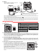
*** 13.8VAC
(18VAC max)
120V AC
* Gel-filled butt
connectors
(EWP only)
Gel-filled butt
connectors
(EWP only)
Red
Green
** Earth
Ground
(optional)
(Spade connector
included)
Multi-Line
Phone
C.O.
Line
C-1000B Controller
Single Line
Phone
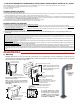
IMPORTANT: Electronic devices are susceptible to lightning and power sta-
tion electrical surges from both the AC outlet and the telephone line. It is rec-
ommended that a surge protector be installed to protect against such surges.
!
Important: Do NOT install a W-3000 on a telephone line
without a C-1000B Controller (DOD# 155).
Sw 1
OFF
ON
Ring Cadence
Standard: (1 second ON, 3 seconds OFF)
Custom (2 short rings): 0.5 seconds ON, 0.25 seconds OFF,
0.5 seconds ON, 3 seconds OFF
B. Wiring
P
P
r
r
o
o
g
g
r
r
a
a
m
m
m
m
i
i
n
n
g
g
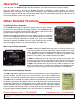
D. Microphone and Speaker Volume Adjustment POTs
In certain noisy locations, the microphone volume may need to be
decreased. A microphone POT (see right) is provided on the W-3000’s circuit
board to increase or decrease the microphone volume. However, in extreme-
ly noisy locations the microphone POT adjustment may not be enough to
allow two-way talk path. In this case the “Push-to-Talk” mode should be used
as shown above (see section C above).
Note: Both POTs come factory set in the middle position. A speaker volume
POT is also provided for increasing or decreasing the speaker audio as
needed.
B. Handsfree Operation (Dip Switch 4 - OFF)
When the “Call” button is pressed, the call progress LED will turn off and the W-3000 will begin generating a 20 Hz ring
signal. The caller at the W-3000 will hear an audio ring back signal while the LED flashes. When the inside party has
answered, the LED will light until the inside party hangs up. At that point, the LED will turn off for approximately one
second and then light steady to illuminate the W-3000 after dark.
C. Push-To-Talk Operation (Dip Switch4-ON)
In extremely noisy locations, the “Push-to-Talk” mode should be used. To switch to the “Push-to-Talk” mode, place DIP
switch 4 in the ON position (see Dip Switch Programming). To initiate a call, momentarily press the “Call” button to
generate the ring signal. After the inside party has answered, press and hold the call button to talk. Release the call
button to listen.
A. DIP Switches
1 2 3 4
ON
DIP
Switches
Sw 3
OFF
OFF
ON
ON
Ring Output
2 Ring
3 Rings
10 Rings
30 Rings
Sw 2
OFF
ON
OFF
ON
Communication Mode
Normal Handsfree Mode
Push-to-Talk Mode
Sw 4
OFF
ON
Speaker
Volume
Microphone
Volume
** Note: To increase surge protection, loosen the PCB mounting screw labeled (as shown above) and fasten a wire with spade terminal (includ-
ed) from the mounting screw to Earth Ground (grounding rod, water pipe, etc.)
* Note: The gel-filled (water-tight) butt connectors are designed for insulation displacement on 19-26 guage wire with a maximum insulation of 0.082
inches. Cut off stripped wire ends prior to terminating.
*** Warning: The power run wire length is limited to 125 ft of 24 AWG wire. Longer power runs will require heavier gauge wire (doubling pairs)
and/or a higher voltage power adapter. Power runs from 125 - 250 ft of 24 AWG wire are possible using a Radio Shack 18VAC adapter (part # 273-
1690). Voltage at the doorbox power input connections must not exceed 18VAC RMS.