Viking Installation Guide Viking Range Corporation 111 Front Street Greenwood, Mississippi 38930 USA (662) 455-1200 For product information, call 1-888-VIKING1 (845-4641) or visit the Viking Web site at vikingrange.
Table of Contents IMPORTANT–Please Read and Follow! Warnings & Important Information_____________________________________________________ 3 Professional & Professional Integrated Side-by-Side Dimensions & Specifications (Professional 42” & 48”) ________________________________ 6 Dimensions & Specifications (Professional Integrated 42” & 48”) _______________________8 Cutout Dimensions (42”) _________________________________________________________10 Anti-Tip Dimensions (42”) _______________________________
IMPORTANT–Please Read and Follow! IMPORTANT–Please Read and Follow! A GFI shall be used if required by NFPA-70 (National Electric Code), federal/state/local laws, or local ordinances. • The required use of a GFI is normally related to the location of a receptacle with respect to any significant sources of water or moisture. • Viking Range Corporation will NOT warranty any problems resulting from GFI outlets which are not installed properly or do not meet the requirements below.
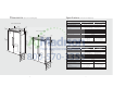
Dimensions Specifications (Professional Side-By-Side) (Professional Side-By-Side) 42” Professional Side-By-Side 42” Professional Description (104.1 (9.1 cm2” ) /2” 1–1cm) cm) (3.8 42” (106.7 cm) Cutout width Cutout height Cutout depth Electrical requirements 48” Professional 9–5 / (23.332” 115 volt, 60 Hz, 15 amp dedicated circuit; 3-wire cord with cm) 47” (119.4 3–19/3 (9.1 cm2” ) 1– cm) cm) Requirements (3.8 48” (121.9 cm) 75–1 (192 5/16” .9 cm ) 9–5 / (23.
Dimensions Specifications (Professional Side-By-Side) (Professional Side-By-Side) 42” Professional Integrated Side-By-Side Description 42” Professional Integrated VISB542 Overall width Overall height from bottom Overall depth from rear 41 (104.1” cm) 3–19/3 (9.1 cm2” ) /2” 1–1cm) (3.8 42” (106.7 cm) Cutout width Cutout height Cutout depth Electrical requirements 48” Professional Integrated 9–5 / (23.332” cm) 47 (119.4” cm) 3–19/3 2” (9.1 cm ) /2” 1–1cm) requirements (3.
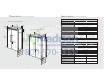
Cutout Dimensions Anti-Tip Dimensions (Professional Side-By-Side) 42” Professional 42” Professional & Professional Integrated 24” ) cm (61.0 (Professional Side-By-Side) Professional Anti-Tip Location See An ti-Tip b oard in Electric Outlet Location stallati on 6” (15.2 9” (22.9 Two 2”x 4” Mounting Boards 3” (7.6 cm) x 3-1/2” (8.9 cm) cm) cm) 3” ) m (7.6 c 9” (22.9 cm) 35” (88.9 cm ) 3–1/ 82 (210 –7/8” .5 anti- cm) m 79 (201 –3/8” .6 to cm) m in tip open board .
Cutout Dimensions Anti-Tip Dimensions (Professional Side-By-Side) (Professional Side-By-Side) 48” Professional & Professional Integrated 48” Professional & Professional Integrated 24” (61.0 cm) See An ti-Tip b Professional Anti-Tip Location Electric Outlet Location oard in st allation 6” (15.2 9” (22.9 Two 2”x 4” Mounting Boards 3” (7.6 cm) x 3-1/2” (8.9 cm) cm) cm) 3” ) m 9” (22.9 (7.6 c cm) 41” (104.1 82 (210 –7/8” .5 anti- cm) m (201 84 (213 –1/16” .5 anti- cm) m tip b ax.
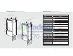
Dimensions Specifications (Professional Bottom-Mount) (Professional Bottom-Mount) 36” Professional Bottom-Mount 36” Professional Description 35” (88.9 cm ) 36” 3–19/3 Overall width /2” 1–1cm) Overall height from bottom Overall depth from rear (3.8 (91.5 cm (9.1 cm2” ) ) 36” Professional Integrated 9–5/3 Cutout wdth Cutout height Cutout depth Electrical requirements 2 (23.3 cm” ) /2” 35” 5 (13 2” (88.9 cm ) 36” 3–19/3 1–1cm) (3.8 (91.5 cm (9.
Cutout Dimensions Anti-Tip Dimensions (Professional Bottom-Mount) 36” Professional & Professional Integrated 36” Professional & Professional Integrated 24” ) cm (61.0 See An ti-Tip b oard in Professional Anti-Tip Location Electric Outlet Location stallati on (Professional Bottom-Mount) 6” (15.2 Two 2”x 4” Mounting Boards 3” (7.6 cm) x 3-1/2” (8.9 cm) cm) 9” (22.9 cm) 3” ) m 9” (22.9 cm) (7.6 c 79–3 .6 to bo cm) min . anti- ttom of tip b oard 82 (210 –7/8” .5 anti- cm) min tip .
Cabinet Information Cabinet Information (Professional) Professional models fit “semi-flush” in standard 24” (61.0 cm) deep cabinet openings. The door face protrudes 2-1/2” (6.4 cm) from the cabinet face. The handle protrudes an additional 2-1/2” (6.4 cm) into the room. (Professional) Professional models fit “semi-flush” in standard 24” (61.0 cm) deep cabinet openings. The door face protrudes 2-1/2” (6.4 cm) from the cabinet face. The handles protrude an additional 2-1/2” (6.4 cm) into the room.
Cabinet Information (Professional Integrated) Professional Integrated models fit flush in standard 24” (61.0 cm) deep cabinet openings with no protrusion into the room except the handle protrudes 2-1/2” (6.4 cm) into the room. Cabinet Information (Professional Integrated) Professional Integrated models fit flush in standard 24” (61.0 cm) deep cabinet openings with no protrusion into the room except the handle protrudes 2-1/2” (6.4 cm) into the room.
Dimensions Specifications (Designer Side-By-Side) (Designer Side-By-Side) 42” Designer Side-By-Side Description Designer 42” Overall width 41 3–1/2 (8.9 cm” ) 42 (106.7” cm) (104.1” cm) Overall height from bottom Overall depth from rear /2” 1–1 ) (3.8 cm Cutout width Cutout height Cutout depth Electrical requirements Designer 48” 9–5 / (23.332” cm) 47 3–1/2 (8.9 cm” ) 48 (121.9” cm) (119.4” cm) Maximum amp usage Inlet water /2” 1–1 ) (3.8 cm Requirements 75–1 (192 5/16 .
Cutout Dimensions (Designer Side-By-Side) 24” ) .0 cm (61 Anti-Tip Dimensions (Designer Side-By-Side) 42” Designer 42” Designer See An ti-T Electric Outlet Location ip boa rd inst allation 6” (15.2 9” (22.9 cm) Anti-Tip Location cm) 9” (22.9 cm) 79 (201 –3/8” .6 to bo cm) min . 82 (210 –7/8” .5 anti- cm) min tip . (3.8 c 35” (88.9 cm 80–1 (204 84 .6 (213 –1/16” .5 anti- cm) m tip b ax. ) /2” to bo cm) max .
Cutout Dimensions (Designer Side-By-Side) Anti-Tip Dimensions (Designer Side-By-Side) 48” Designer 48” Designer 24” ) cm (61.0 See An ti-Tip b Electric Outlet Location oard in st allation 6” (15.2 9” (22.9 Anti-Tip Location cm) cm) 9” (22.9 cm) 79 (201 –3/8” .6 to bo cm) min . 82–7 (210 .5 /8” ning oard & heig ht (3.8 c 41” (104.1 cm) 80 (204 –1/2” .6 to bo cm) max 84 (213 –1/16” .5 anti- cm) m tip b ax. ope 2” 1–1/ m) anti- ttom of tip b oard anti- cm) min tip open board .
Dimensions Specifications (Designer Bottom-Mount) 36” Designer Bottom-Mount Designer 36” Description Overall width 35” (88.9 c m) 36” /2” 1–1cm) (3.8 Overall height from bottom Overall depth from rear (91.5 c 3–1/2 m) (8.9 cm” ) (Designer Bottom-Mount) 9–5/3 2 (23.3 c ” m) Cutout width Cutout height Cutout depth Electrical requirements Maximum amp usage Inlet water Requirements DDBB536 36” (91.5 cm) 82-3/4” (210.2 cm) min. to 84-1/16” (213.5 cm) max.
Cutout Dimensions (Designer Bottom-Mount) Anti-Tip Dimensions (Designer Bottom-Mount) 36” Designer 24” (61.0 cm) See An ti-Tip b oard in 36” Designer Electric Outlet Location stallati on 6” (15.2 cm) Anti-Tip Location 9” (22.9 cm) 79 (201 –3/8” .6 to bo cm) min . 82 (210 –7/8” .5 anti- cm) min tip . open board & ing h eigh t 80 (204 –1/2” .6 to b cm) ma 84 (213 –1/16” .5 anti- cm) m tip b ax. ope ning oard & heig ht 2” 1–1/ m) (3.8 c anti- ttom of tip b oard x.
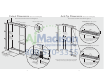
Cabinet Information Cabinet Information (Designer) Designer models fit flush in standard 24” (61.0 cm) deep cabinet openings with no protrusion into the room except 2-1/2” (6.3 cm) handle depth. Top View (Designer) Designer models fit flush in standard 24” (61.0 cm) deep cabinet openings with no protrusion into the room except 2-1/2” (6.3 cm) handle depth. Overlapping cabinet doors Top View Wall 3/4” Wall (1.9 cm) space if 24” (61.0 cm) standard cabinet depth is used 1” (2.
Custom Side Panel Dimensions (Professional) 3/16” (0.5 cm) Back filler panel ” 16 -7/ m) 227.0 c Custom Side Panel Dimensions (Designer & Professional Integrated) 3/4” (1.9 cm) End panel Z-Bracket /4” 1/4” 3/4” (0.6 cm) (1.9 cm) End panel -3 ) 21.2 cm 6”cm) .2 (15 1” (2.5 cm) (55 (5 5/32” (0.4 cm) 4” -3/ ) 21.2 cm ” 16 -7/ m) 227.0 c (55 (5 (2182-7 0.5 /8 cm ” )m in. (21 84-1to 3.5 /1 cm 6” )m ax .* (2182-7 0.5 /8 cm ” )m in. (21 84-1to 3.5 /1 cm 6” )m ax .* 6”cm) .
General Information General Information this appliance be provided. This appliance is equipped with a power supply cord having a 3-prong grounding plug. To minimize possible shock hazard, the cord must be plugged into a mating 3-prong, grounding-type wall receptacle. Do not use an extension cord. Area Requirements Verify the following: • Unit can fit into residence and can be moved around corners and through doorways.
Installation General Information 2a 1 TIP OVER HAZARD • Most of the unit’s weight is at the top. Extra care is needed when moving the unit to prevent tipping. Appliance is top heavy and tips easily when not completely installed. Keep doors closed until appliance is completely installed and secured per installation instructions. Use two or more people to move and install appliance. Failure to do so can result in death or serious injury.
Hinge Adjustment 6 5 Front of unit 10a 9 2 2 3” 1 1 Remove four side screws and remove unit top. 3 Plug in power cord to verify operation. NOTE: Make sure power switch is in the “On” Position. Loosen the four hinge screws. Adjust door. Retighten four hinge screws. 7 Place unit within 3” of being flush with cabinets. NOTE: To avoid cabinet damage, place cardboard between cabinets and unit. When moving unit, do not crimp, kink or crush water supply line. 10b 11 1 2 Replace unit top.
Door Stop Adjustment 14 (Side-by-Side) 20 15 21 1 1 90˚ 110˚ 120˚ 3 2 2 Turn on water supply and check for leaks. Lift unit off rollers to desired height and level unit using a 5/16” head wrench. NOTE: DO NOT use an electric device. Overtightening can cause damage. 16 17 Open refrigerator door so door stop and shoulder screw are accessible. NOTE: Shoulder screw should be in 110˚ door opening position. Door Stop Adjustment Remove shoulder screw and place in 90° or 120° position.
Water Filter Installation (Side-by-Side with Dispenser) Water Filter System Specification and Performance Data Sheet 25 24 This system has been tested according to NSF/ANSI 42/53 for reduction of the substances listed below. The concentration of the indicated substances in water entering the system was reduced to a concentration of less than or equal to the permissible limit for water leaving the system, as specified in NSF/ANSI 42/53.
Final Installation 28 29 Replace top air grille. Performance Checklist Using an 8” magnetic nut driver, replace the two 1/4” screws. 30a 30b (Professional) Replace the center grille louver. (Designer) Replace the center grille louver. 31 32 h Verify cabinet size. h Align/square door(s). h Verify electrical supply and water supply (if applicable). h Verify drain pan is properly installed and no leaks on water connection. h Install anti-tip device(s) and verify unit is secure.
Verify Operations Service & Registration Control Panels Only authorized replacement parts may be used in performing service on the appliance. Do not repair or replace any part of the appliance unless specifically recommended in the manual. All other servicing should be referred to a qualified technician. Bottom Mount Side by Side Record the following information indicated below. You will need it if service is ever required.
50 51