Installation 15”W.
Table of Contents Warnings & Important Safety Instructions ______________________________________________________________________3 Dimensions (Professional) ____________________________________________________________________________________5 Dimensions (Custom Panel) __________________________________________________________________________________6 Specifications ______________________________________________________________________________________________7 Cutout Dimensions ______________________________
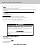
Important - Please read and Follow! • • • • • Before beginning, please read these instructions completely and carefully. DO NOT remove permanently affixed labels, warnings, or plates from the product. This may void the warranty. Please observe all local and national codes and ordinances. Please ensure that this product is properly grounded. The installer should leave these instructions with the consumer who should retain for local inspector’s use and for future reference.
Important - Please read and Follow! PROPER DISPOSAL (OF OLD REFRIGERATION UNIT) DANGER RISK OF CHILD ENTRAPMENT Before You Throw Away Your Old Refrigeration Unit: • Take off the doors. • Leave the shelves in place so that children may not easily climb inside. IMPORTANT: Child entrapment and suffocation are not problems of the past. Junked or abandoned refrigeration units are still dangerous... even if they will sit for “just a few days.
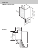
Dimensions FGNI/FPNI w/ Professional door panel 14 (37-7/8 .8 ” cm ) 30 33 - (86-7/8 .0 ” mi cm) n. 34 to (88-7/8 .6 ” ma cm) x. (775/16 .0 ” cm ) /4”) 1 9 cm 1 .9 48 ( /4”) 3 2 cm 2 .8 7 (5 /4”) 1 5 cm 2 .1 64 ( 14-3/4” (37.5 cm) Door Swing 3-7/8” (9.8 cm) Floor drain access hole 20-3/8” (51.6 cm) 22-3/4” (57.8 cm) 2-1/2” (6.4 cm) 115.0° 90.0° 5 37-3/4” (95.
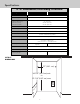
Dimensions FGNI/FPNI w/ Custom door panel 14 (37-7/8 .8 ” cm ) 33 30 (86-7/8 .0 ” mi cm) n. 34 to (88-7/8 .6 ” ma cm) x. -5/ (77 16 .0 ” cm ) /4”) 1 9 cm 1 .9 48 ( /4”) 3 2 cm 2 .8 57 ( 14-3/4” (37.5 cm) 3-7/8” Door Swing (9.8 cm) Floor drain access hole 20-3/8” (51.6 cm) 22-3/4” (57.8 cm) 115.0° 37-3/4” 90.0° (95.
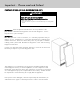
Specifications 15”W. Undercounter/Freestanding Ice Machine Description FGNI515 FPNI515 Overall width 14-7/8” (37.8 cm) Overall height 33-7/8” (86.0 cm) min. to 34-7/8” (88.6 cm) max. Overall depth from rear (without door panel) (with door panel) (with door handle) 22” (55.9 cm) 22-3/4” (57.8 cm) 25-1/4” (64.1 cm) Cutout width 15” (38.1 cm) Cutout height 34-1/4” (86.4 cm) min. to 35-1/4” (89.5 cm) max. Cutout depth 24” (61.
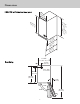
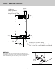
Drain / Electrical Location 1/4” (0.6 cm) O.D. Copper Water Inlet Compression Fitting Provided 2-3/4” (7.0 cm) 5-1/8” (13.0 cm) 2-1/2” (6.4 cm) 115V Power Cord 3-1/4” (8.3 cm) 7-1/2” (19.1 cm) 11-5/8” (29.5 cm) Drain Access - Flexible Tubing 3/8” (.95 cm) I.D. Pump Model (included) 5/8” (1.6 cm) I.D. Gravity Model (not included) AIR FLOW The machine takes in room temperature air at the lower right front and forces warm air out the lower left front.
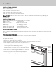
Installation INSTALLATION OVERVIEW The ice machine must: • Be connected to cold, potable water. • Be connected to a drain. • Be connected to the proper power supply. • Be able circulate air through the vents at the front. Note: DO NOT build in so that the door is recessed. Door is meant to be flush with surronding cabinetry, but not recessed.
Installation (con’t) CUSTOM PANEL A custom panel of wood or other material not exceeding 15 lb can be attached to the door. Attachment is from the ice side of the door. Holes are provided in the door for this purpose. To • • • create and attach a custom panel: Panel width: 14-7/8” (37.9 cm) Panel height: 30-5/16” (77.0 cm) Panel thickness: 5/8” (14.5 cm) to 3/4” (1.9 cm) 1. Measure overall height of cabinet opening where ice machine will be (floor to botom of countertop edge). 2.
Installation (con’t) CUSTOM PANEL DIMENSIONS 13-9/16” (34.4 cm) 6-25/32” (17.7 cm) 13/16” (2.4 cm) 4-1/8” (10.5 cm) 8-1/4” (20.9 cm) 13/32” (1.3 cm) 14-11/16” (37.3 cm) ø 1/8” TYP. (10) 30-5/16” (77.0 cm) 13-31/64” (34.3 cm) 13/32” (1.3 cm) 14-7/8” (37.
Installation (con’t) DOOR PANEL ATTACHMENT Use Upper Hole at the Top Accessory Door Panel Gasket Machine Screw Use Lower Hole at the Bottom Hole Plug Cover 12
Installation (con’t) DOOR SWING CHANGE The door can be attached to open with hinges on the left or right using new brackets shipped loose in the ice bin. Retain all screws for re-use. To change: 1. Remove inner screw holding each hinge to cabinet, loosen the outer screw. 2. Slide hinges to the side and remove door from cabinet. Remove outer screws loosened in step 1 from both hinge brackets. 3. Remove two screws securing top panel to back, pull top panel back and remove from cabinet. 4.
Installation (con’t) WATER & DRAIN INSTALLATION The recommended water supply tubing is 1/4” OD copper. Stainless steel flex or reinforced PVC tube may also be used. Install an easily accessible shut-off valve between the supply and the unit. This shut-off valve should not be installed behind the unit. The water connection is at the back of the cabinet. Connect using a compression fitting, one is supplied tied to the water inlet tube at the back of the cabinet.
Installation (con’t) GRAVITY DRAIN PUMP MODEL DRAIN INSTALLATION CAUTION Restrictions in the drain system to the machine will cause water to back up into the ice storage bin and melt the ice. Gravity drain tubing must be vented, have no kinks and slope to the building drain. Air gaps are typically required by local code. 1. Place the ice machine in front of the installation opening. Adjust leveling legs to the approximate height. 2. Insert drain tube through the routing hole in the back panel. 3.
Electrical Connection WARNING ELECTRICAL SHOCK HAZARD Failure to follow these instructions could result in fire or electrical shock. The ice machine is supplied with a power cord. DO NOT remove the grounding pin from the cord’s plug. DO NOT use extension cords. Follow all codes. Connect the machine to its own 115 volt, 15 amp circuit. Grounding type wall receptacle FINAL INSTALLATION 1. 2. 3. 4. 5. 6. 7. 8. 9. If the electrical outlet for the ice maker is behind the unit, plug in the unit.
Service Information If service is required, call your authorized service agency. Have the following information readily available. • Model number • Serial number • Date purchased • Name of dealer from whom purchased Clearly describe the problem that you are having.
Viking Range, LLC 111 Front Street Greenwood, Mississippi 38930 USA (662) 455-1200 For product information, call 1-888-(845-4641) or visit our web site at vikingrange.com in the US or brigade.