Installation Guide Microwave Built-In Trim Kit
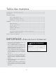
Table of Contents Warnings & Important Information————————————————————————— 2 Specifications—————————————————————————————————— 3 General Information———————————————————————————————— 4 Parts Included in the Kit—————————————————————————— 4 Cabinet or Wall Cutout——————————————————————————— 4 Electrical Outlet Location—————————————————————————— 4 Installation———————————————————————————————————— 5 Mounting Template———————————————————————————— 5 Bottom Duct Assembly——————————————————————————— 6 Mounting Bracket As
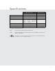
Specifications Microwave Oven Built-In Trim Kit RVM320 / CRVM320 RVMTK330 Overall Width 24" (60.9 cm) 29-1/2" Overall Height from Bottom 13-3/8" (33.9 cm) 17-1/4" Overall Depth from Rear 19-1/8" (48.7 cm) Oven Interior Width Height Depth Overall 17-3/8" 10-1/2" 18-5/8" 2.0 cu. ft. (74.9 cm) (43.7 cm) NA (44.1 cm) (26.6 cm) (47.3 cm) NA Electrical Requirements 120VAC/60 Hz NA Max. Amp Usage 1.5 KW 13 amps NA Approx. Shipping Wt. 46 lbs. (20.9 kg) 15 lbs. (6.
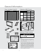
General Information Parts Included in the Kit Cabinet or Wall Cutout 1) Frame Assembly: QTY 1 Item Part Name QTY 1 Frame Assembly 1 2 Bottom Duct 1 3 Mounting Bracket 2 4 Screw A :1-3/16" length 2 5 Screw B: 1-3/4" length 4 6 Side Decoration (Surface Mount Only) 2 7 Surface Mounting Template 1 Flush Mounting Template 1 8 2) Bottom Duct Assembly: QTY 1 1) Frame Assembly: QTY 1 Flush Mount Surface Mount Minimum 17-5/16" (439.8mm) 16-9/16" (420.
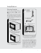
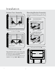
Installation 3 Align the template corresponding to the required mounting method to the center of the cabinet. Make sure that the template is level with the floor. Tape it into place. Cut the cabinet opening along the lines specified on the template. Leave Illustration 2 template taped in place. a. A figure 2 A SIDE SPACER—2 REQUIRED. Must protrude from edge of cabinet cutout towards center as shown. figure Determine which mounting method to use based on the required configuration.
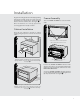
Installation Illustration 6 - for Flush Mount Bottom Duct Assembly Mounting Bracket Assembly Position the mounting brackets to align with the predrilled holes that were drilled with the mounting template. figure 4 CENTER THE BOTTOM DUCT A Flush mount BRACKET figure 6 SCREW A make bottom flange flush with bottom spacer bottom duct Illustration 7 - for Surface Mount Place the Bottom Duct in the cabinet opening. For Flush Mount, it will rest on the bottom spacer centered with the cabinet.
Frame Assembly Align the mounting brackets horizontally by sliding them back and forth along the screw slots until the brackets are exactly 27-1/2" apart and equal distance from the cabinet sides. See figure 7. Turn over FRAME ASSEMBLY to locate the 4 ball studs. Once the brackets are correctly positioned, securely tighten the four (4) screws B. ! figure Cabinet Installation CABINET INSTALL Place the oven adjacent to the wall or cabinet opening. Plug the power cord into the electrical outlet.
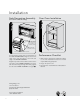
Installation Side Decoration Assembly Over Oven Installation (For Surface Mount Only) # figure figure " ALIGN TOP SURFACE OF SIDE DECORATION TO TOP SURFACE OF FRAME ASSEMBLY FRONT INNER EDGE OF SIDE DECORATION 2" (5.1 cm) for 30" W Lower Oven FRONT SIDE EDGE OF FRAME ASSEMBLY Performance Checklist Peel the backing off the tape on the backside of the SIDE DECORATIONS. Align the front inner edge of the side decorations to the front side edge of the FRAME ASSEMBLY. 1.
Guide d’installation Kit de garniture à encastrer pour four à micro-ondes
Table des matières Avertissements et Information importante—————————————————————— 10 Spécifications—————————————————————————————————— 11 Information générale Pièces comprises dans le kit———————————————————————— 12 Découpe de l’armoire ou du mur—————————————————————— 12 Emplacement de la prise électrique————————————————————— 12 Installation ——————————————————————————————————— 13 Gabarit de fixation————————————————————————————— 13 Pose du conduit inférieur—————————————————————————— 14 Brides de fixation——————
Specifications Four à micro-ondes Kit de garniture à encastrer RVM320 / CRVM320 RVMTK330 Largeur hors tout 24 po (609 mm) 29-1/2 po (749 mm) Hauteur hors tout depuis le bas 13-3/8 po (339 mm) 17-1/4 po Profondeur hors tout depuis l’arrière 19-1/8 po (487 mm) Intérieur du four Largeur Hauteur Profondeur Hors tout 17-3/8 po 10-1/2 po 18-5/8 po 2 pi3 Alimentation électrique 120VAC/60 Hz S/O Max. Ampèrage max. 1,5 KW 13 amps S/O Poids approx. à l’expédition. 46 lb.
Information générale Pièces comprises dans le kit 1) Frame Assembly: QTY 1 Numéro Nom de pièce Qté 1 Cadre de porte 1 2 Conduit inférieur 1 3 Bride de fixation 2 4 Vis A : longueur 1-3/16 po (30,2 mm) 2 5 Vis B : longueur 1 3/4 po (44,5 mm) 4 6 Décorations latérales (pour fixation en surface uniquement) 2 7 Gabarit de fixation en surface 1 8 1) Frame Assembly: QTY 1 Découpe de l’armoire ou du mur 2) Bottom Duct Assembly: QTY 1 Dimensions de la découpe Minimum Hauteur A Fixatio
Installation 3 Aligner le gabarit correspondant à la méthode de fixation requise avec le centre de l'armoire. Veiller à ce que le gabarit soit horizontal. Coller en place avec du ruban adhésif. Découper l'ouverture de l'armoire selon les lignes indiquées sur le gabarit. Laisser le gabarit en place. A dépasser du bord de la découpe de l’armoire vers le centre comme illustré.
Installation Illustration 6 - for Flush Mount Conduit inférieur Brides de fixation Placer les brides de fixation pour les aligner avec les trous percés à l’aide du gabarit. figure 4 6 CENTRER CENTER THE LE CONDUIT BOTTOM DUCT VIS A Bride fixée encastrée figure INFÉRIEUR A CONDUIT INFÉRIEUR FAIRE AFFLEURER LA BRIDE INFÉRIEURE AVEC L'ENTRETOISE INFÉRIEURE Illustration 7 - for Surface Mount VIS B Placer le conduit inférieur dans l’ouverture de l’armoire.
Cadre de porte Aligner les brides de fixation horizontalement en les faisant glisser vers l'avant et l'arrière le long des fentes de vis jusqu'à ce que les brides soient exactement séparées de 27-1/2 po (698,5 mm) et à égale distance des côtés de l'armoire. Voir figure 7. Retourner le CADRE DE PORTE pour repérer les quatre pivots à rotule. ! figure Une fois les brides correctement placées, bien les fixer avec quatre (4) vis B.
Installation Décorations latérales Installation au dessus d'un four (pour fixation en surface uniquement) " figure figure # ALIGNER LA SURFACE SUPÉRIEURE DE LA DÉCORATION LATÉRALE AVEC LA SURFACE SUPÉRIEURE DU CADRE DE PORTE BORD INTÉRIEUR AVANT DE LA DÉCORATION LATÉRALE BORD INTÉRIEUR AVANT DU CADRE DE PORTE 5,1 cm (2 po) pour un four inférieur de 91,4 cm (30 po) de large Retirer le papier dorsal du ruban au verso des DÉCORATIONS LATÉRALES.