Installation Guide 100/300/500 Series Outdoor Grill Conversion Kits
IMPORTANT: PLEASE READ AND FOLLOW 1. Before beginning, please read these instructions completely and carefully. 2. Do not remove permanently affixed labels, warnings, or plates from product. This may void the warranty. 3. Please observe all local and national codes and ordinances. CAUTION: Before proceeding with the conversion, shut off the gas supply to the appliance prior to disconnecting the electrical power.
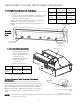
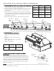
VGBQ/CVGBQ T/T1/E AND 100/300 SERIES CONVERSIONS To convert grill burners, side burner and smoker burner: 1. Remove all grates, flavor generators and stainless steel burners from the unit. 2. Look into the burner box back toward the control panel in order to located the orifice hoods. Remove the gas orifice hoods located on the grill burner valves. 3. Replace the orifice hoods with the correct gas orifice hoods supplied in the conversion kit. (See chart) 4.
FOR E1/E2 AND 500 SERIES GRILLS Depending on the grill model, all orifices in the kit may not be used.
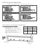
To convert the rotissiere infrared burner: 1. Remove the back cover from the unit to expose the orifice hood to the infrared burner. 2. Remove the gas orifice hood located on the grill. 3. Replace with the gas orifice hood supplied in the conversion kit. 4. Replace the back cover.
VGIQ/CVGIQ E1/E2 AND 500 SERIES CONVERSIONS To convert grill burners, TruSearTM burner, side burner and smoker burner: 1. Remove all grates, flavor generators and stainless steel burners from the unit except for ones over TruSearTM infrared burner. 2. Remove control panel to expose the burner valves. Remove the orifice hoods located on the valve for the grill burners, side burners, and smoker burner. 3.
Natural or LP/Propane Connection Natural Fixed Connection: Standard Residential 1/2” gas service line - 1/2” NPT male with 7/8” flare adapter. 4.0” W.C.P. Operating Pressure / 6” to 10” W.C.P. Supply Pressure LP/Propane Fixed Connection: Standard Residential 1/2” gas service line - 1/2” NPT male with 3/8” flare adapter. 10.0” W.C.P. Operating Pressure / 11” to 14” W.C.P. Supply Pressure LP/Propane Cylinder Connection: 1/2” NPT male with 3/8” flare adapter 10.0” W.C.P.
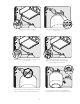
3 4 Apply the soap solution to fittings. Turn cylinder valve knob counter clockwise one turn to open. 5 6 Bubbling bubbles in the soap solution indicates that a leak is present. Stop a leak by tightening the loose joint or by replacing the faulty part with a replacement part recommended by the manufacturer. 7 1 8 2 Do not attempt to repair the cylinder valve if it should become damaged. The cylinder must be replaced. If you are unable to stop a leak, shut off the gas at the cylinder valve.
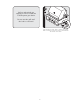
Call an authorized gas appliance service technician or LP/Propane gas dealer. Do not use the grill until the leak is corrected. OF F 2 1 After checking for leaks, push in and turn any control knob to release the pressure in the hose and manifold. Turn off the control knob.
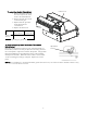
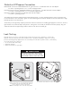
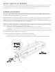
INITIAL IGNITION OF BURNERS All burners are tested before leaving the factory. Field adjustments may be necessary for proper mixture of gas and air for proper operation. When the grill is connected to the gas service, it should be adjusted by a qualified technician. For lighting instructions, refer to the Outdoor Gas Grill Use and Care Manual.
1-1/2” (3.8 cm) Air Shutter 3/8” (0.95 cm) Fig. 3 SIDE BURNER Orifice (If applicable) Spark Ignitor Adjustment Occasionally a burner may not ignite within a few seconds after turning the appropriate control knob counter-clockwise. To adjust the spark ignitor, use a small needle nose plier to turn the metal head of the ignitor towards the port (opening) on the burner. DO NOT TURN THE IGNITOR BY THE CERAMIC BASE. This could cause damage to the spark ignitor.
Viking Range, LLC 111 Front Street Greenwood, Mississippi 38930 USA (662) 455-1200 For product information, call 1-888-845-4641 F21028C EN (020117)