Table of Contents Farmings & Important Safety Instructions Dimensions.
IMPORTANT—Read and Follow! Before beginning, please read these instructions completely and carefully. * DO NOT remove permanently affixed labels, warnings, or plates from product. This may void the warranty. All local and national codes and ordinances must be observed. Installation must conform with local codes or in the absence of codes, the National Fuel Gas Code ANSI Z223.1 PASSING.
IMPORTANT—Read and Follow! A GFI shall be used if required by PAN-70 (National Electric Code), federal/state/local laws, or local ordinances. ® The required use normally related to the location of a receptacle with respect to any significant sources of water or moisture. * Viking Range, LLC will NOT warranty any problems resulting from GFI outlets which are not installed properly or do not meet the requirements below.
A DANGER CHEMICAL HAZARD To avoid risk of property damage and/or personal injury or death; this appliance is not too be used as a heating source. ® Benzene is a chemical which is part of the gas supply to this cooking product, which is consumed in the flames during combustion, Exposure to a small amount of benzene is possible if a gas leak occurs. Formaldehyde and soot are byproducts of incomplete combustion.
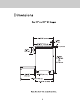
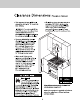
Dimensions Gas 30” and 36" W. Ranges 289718% 12 6] —> 4 em (67.2 {¥1.1 em) min. Ll 37 {54.0 cra} cornet, — >« {49.2 cm} ! (654 cm) —» (114.6 em}) P [— (51.8cm} Note: Unit shown with standard island trim.
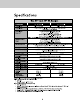
Specifications (75.9 em) (1.1 em) To top of side trim (91.1 cm) min. 37" (94.0 cm) max. Legs adjust (2.9 cm) To end of side panel (61.8 cm) To front of door {(65.4 cm) Te end of landing ledge 71.2 em) To end of door handle (72.9 cm) *Add 1" to overall depth for ranges with blackguards installed against a combustible wall, To top of island trim add 17 (2.5 cm) To top of blackguard add 8" (20.3 cm) To top of high shelf add (59.
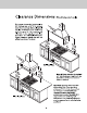
Clearance Dimensions bromide to cabinets This range may be installed directly adjacent to existing 36" (91.4 cm) high base cabinets. IMPORTANT: The side trim MUST be 3/8" (.95 cm) above the adjacent base cabinet counter top. This can be accomplished by raising the unit using the adjustment spindles on the legs. The range CANNOT be installed directly adjacent to sidewalls, tall cabinets, tall appliances, or other side vertical surfaces above 36" {91.4 cm} high. There must be a minimum of 67 (15.
Clearance Dimensions wood/composite overlay) The bottom of a standard hood should be 30" (76.2 cm) min. to 36" (91.4 cm) max. above the counter top. This would typically result in the bottom of the hood being 66" (167.6 cm) to 72" (182.9 cm) above the floor. Refer to the range hood installation instructions for additional information. These dimensions provide for safe and efficient operation of the hood. Note: Minimum clearance for back wale is 0" with blackguard or high-shelf.
Electrical & Gas Requirements Electrical Requirements Check your national and local codes regarding this unit. This range requires 120VAC/60 Hz; 4 ft. {(121.9 cm), 3-wire cord with grounded 3-prong plug attached to unit. See “Electrical Connection” section for grounding instructions. Must be fused separately from any other circuit.
Electrical & Gas Requirements Flexible Connections: In Canada: CAN 1-6, 10-88 metal If the unit is to be installed with flexible connectors for gas appliances and CAN couplings and/or quick-disconnect fittings, 1-6.9 M79 quick disconnect devices for use the installer must use a heavy-duty AGA with gas fuel. design-certified flexible connector of at least 1/2* (1.3 cm} ID NPT {with suitable strain In Massachusetts: This appliance must be reliefs) in compliance with ANSI 721.
General Information READ AND FOLLOW ALL WARNING AND CAUTION INFORMATION WHEN INSTALLING THIS APPLIANCE. * All openings in the wall behind the appliance and in the floor under the appliance must be sealed. * Do not obstruct the flow of combustion and ventilation air. Avoid any damage to oven vents. The vents need to be unobstructed and open to provide proper airflow for optimal oven performance. The cooling fan should be operating when the unit is in operation.
Installation DO NOT use the handle or oven door to lift the oven. Remove door before installation to ensure that it is not used to lift the unit. DO NOT lift or carry the door by the handle. Removing the door must be done by your dealer, a qualified licensed plumber, or certified gas installer. Door Removal Open door compliantly. Place pins, supplied with unit, in pin hole. For personal safety, ONLY use pins supplied with the unit. L Remove hinge trim screws. Take off hings trim.
Legs are packed in Styrofoam top pack. Note: It is strongly recommended Note: Lags should be installed near to whets that a pallet or lift jack be used rather than tilting. appliance is to be used, as they are Raise unit about a foot. Unscrew temporary legs from not secure for long transit. couplings. Craw legs into couplings on all Lower range gently to keep any undue strain from four comers. legs and internal mounting hardware.
Leveling/Adjustments/Alignment Measure the four comers in cutout area to verify if For uneven or sloped floors, level unit with metal shims flooring is level. only, as the adjustment required may excess the thread available in the lag. Check that unit is level side to side and front to back. Side trim of the high comer must be 3/8" (0.95 ¢cm) above counter top. I leveling is required, move unit out of opening. Lift unit and prop on wood blocks.
Leveling/Adjustments/Alignments (cont.) Set the high corner of range so that the top of side trim is 3/8" (0.95 cm) above counter top. Level range to high comer.
Anti-tip Device Installation Wall Mount A WARNING TIPPING HAZARD To reduce the risk of property damage or personal injury; install anti-tipping device provided in accordance with the installation instructions in this document. Device must be engaged properly to prevent product from tipping over. Measure from floor to bottom of the anti-tip opening located on the back of tangs. This will be measurement (A}, Locate anti-tip bracket on rear wall with the top left coma at measurement &) plus 1/4" (.
Connecting Gas & Electric A DANGER GAS LEAK HAZARD . To avoid risk of personal injury or Note: Refer fo electrical and gas death; leak testing of the requirements section for proper appliance must be conducted installation information, according to the manufacturer's instructions. Before placing appliance in operation, always check for gas leaks with soapy water solution. + DO NOT USE AN OPEN FLAME TO CHECK FOR GAS LEAKS. Connect gas and electrical.
Final Installation _Slide range into place. Be sure . Buber caps and boomer bowls are packed in Styrofoam wall anti-tip bracket slides into the anti-tip opening top pack with the grates. Place boomer bowl in grate and floor natl-tip hook and bracket are engaged. support and boomer cap on top of boomer. Place burner grate over boomer cap and on top of grate support. Check that unit is level side to side and front to back. The side trim must be 3/8” {0.95 cm) above counter top.
Door Replacement and Adjustment Reattach door te range. Close door. f the door sends to be adjusted, loosen hings trim screws located in step 2. Adjust the screws located between the door and kick plate using a 5/32" hex head Allen wrench. After adjustment, tighten hinge trim screws.
Final Preparation All stainless steel body parts should be wiped with hot, soapy water and with a liquid cleaner designed for this material. If buildup occurs, DO NOT use steel wool, abrasive cloths, cleansers, or powders! If it is necessary to scrape stainless steel to remove encrusted materials, soak with hot, wet cloths to loosen the material, then use a wool or nylon scraper.
Service & Registration Only authorized replacement parts may be used in performing service on the appliance. All servicing should be referred to a qualified technician. Contact Viking Range, LLC, 1-888-845-4641, for the nearest service parts distributor in your area or write to: VIKING RANGE, LLC PREFERRED SERVICE 111 Front Street Greenwood, Mississippi 38930 USA Record the information indicated below. You will need it if service is ever required.
Viking Range, LLC 111 Front Street Greenwood, Mississippi 38930 USA {662) 455-1200 For product information, call 1-888-845-4641 or visit our web site at vikingrange.com in the US or brigade.