
User Manual


8
|
SIDE BURNER ACCESSORY CARE & USE/INSTALLATION
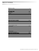
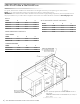
The guides, measurements and dimensions detailed below are designated to assist you with planning your outdoor kitchen.
NOTE: Due to continuing product innovation, specifi cations are subject to change without notice.
IMPORTANT: Please reference the Care & Use / Installation manual for details on gas plumbing requirements, electrical specifi cations and
the proper installation of your outdoor kitchen equipment. This manual can be downloaded from our website at www.vikingrange.com.
S
PE
C
IFI
C
ATI
O
N
S
&
IN
S
TALLATI
ON
**1” (2.54 cm) square hole must be located at rear of
grill cutout.
120V GFI outlet must be located within 6” (15.2 cm) of
the 1” hole.
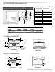
GRILLS
MODEL A B C
VQGI5301 29.00 10.88 24.50
VQGI5361 35.00 10.13 22.00
VQGI5421 41.00 10.88 24.50
VQGI5541 53.00 10.88 24.50
COMPLEMENTARY PRODUCTS
SIDE BURNERS
MODEL A B C
VQGSB5131 12.13 10.63 24.50
VQGPB5201 19.00 10.63 22.00
WARMING DRAWERS
MODEL A B C
VQEWD5301 28.50 10.00 20.50
VQEWD4201 40.25 19.38 24.50
WITH INSULATED JACKET INSTALLED
MODEL A B C
VIJ5301 36.00 11.63 26.50
VIJ5361 42.00 11.63 24.00
VIJ5421 48.00 11.63 26.50
VIJ5541 60.00 11.63 26.50