
Technical data

Connectors and LED signals
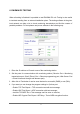
There are the following connectors on the backside of the receiver:
Power supply connector: 12 VDC power supply connector (always use the original
power supply unit provided by manufacturer).
Note: In case of the failure of main power supply unit, the device is able to operate with
power received through USB cable (if USB current is suitable). But long term usage
without main power supply unit is not recommended.
Ethernet connector: 100 Mbit Ethernet connector for network cable.
Mini USB connector: To connect of the USB port of monitoring PC (serial comm).
RS232 connector (only in newer version IP2 receiver): To connect to monitoring PC
(serial communication).
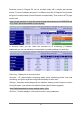
There are the following connectors on the front side of the receiver:
POWER LED: It lights in blue if device is ready to use.
IP LINK LED: It lights green if there is connected network. There is slow red flashings if
network cable is unplugged. Quick red flashings mean received events.
Note: If buzzer is enabled, it sounds with short signals (about 2 beep / sec frequency) if
the network connection is unplugged.
PC LINK LED: It lights green if there is serial connection (USB) with monitoring
software. If there is no connection with monitoring software, this LED is off.
Note: If buzzer is enabled, it sounds with short signals (about 4 beep / sec frequency) if
the connection with monitoring software is failed.
RECEIVER EVENT LED: Amber led flashing means if there is received event through
IP network.
RECEIVER TROUBLE LED: Slow red flashings show the receiver errors (such as
power supply error, monitoring software connection error, IP network error).
Note: The buzzer (if enabled) is continuously active during programming. IP LINK,
RECEIVER EVENT and RECEIVER TROUBLE leds are blinking during programming.
5