
Datasheet

www.vishay.com For technical questions, contact: ind-modules@vishay.com
Document Number: 93565
2 Revision: 03-Nov-08
26MT../36MT.. Series
Vishay High Power Products
Three Phase Bridge
(Power Modules), 25/35 A
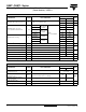
FORWARD CONDUCTION
PARAMETER SYMBOL TEST CONDITIONS
VALUES
UNITS
26MT 36MT
Maximum DC output current at T
C
I
O
120° rect. conduction angle
25 35 A
70 60 °C
Maximum peak, one-cycle
non-repetitive forward current
I
FSM
t = 10 ms
No voltage
reapplied
Initial
T
J
= T
J
maximum
360 475
A
t = 8.3 ms 375 500
t = 10 ms
100 % V
RRM
reapplied
300 400
t = 8.3 ms 314 420
Maximum I
2
t for fusing I
2
t
t = 10 ms
No voltage
reapplied
635 1130
A
2
s
t = 8.3 ms 580 1030
t = 10 ms
100 % V
RRM
reapplied
450 800
t = 8.3 ms 410 730
Maximum I
2
√t for fusing I
2
√tI
2
t for time t
x
= I
2
√t x √t
x
; 0.1 ≤ t
x
≤ 10 ms, V
RRM
= 0 V 6360 11 300 A
2
√s
Low level of threshold voltage V
F(TO)1
(16.7 % x π x I
F(AV)
< I < π x I
F(AV)
), T
J
maximum 0.88 0.86
V
High level of threshold voltage V
F(TO)2
( I > π x I
F(AV)
), T
J
maximum 1.13 1.03
Low level forward slope resistance r
t1
(16.7 % x π x I
F(AV)
< I < π x I
F(AV)
), T
J
maximum 7.9 6.3
mΩ
High level forward slope resistance r
t2
( I > π x I
F(AV)
), T
J
maximum 5.2 5.0
Maximum forward voltage drop V
FM
T
J
= 25 °C, I
FM
= 40 Apk - per single junction 1.26 1.19 V
Maximum DC reverse current I
RRM
T
J
= 25 °C, per junction at rated V
RRM
100 µA
RMS isolation voltage V
INS
T
J
= 25 °C, all terminal shorted; f = 50 Hz, t = 1 s 2700 V
THERMAL - MECHANICAL SPECIFICATIONS
PARAMETER SYMBOL TEST CONDITIONS
VALUES
UNITS
26MT 36MT
Maximum junction and storage
temperature range
T
J
, T
Stg
- 55 to 150 °C
Maximum thermal resistance,
junction to case
R
thJC
DC operation per bridge
(based on total power loss of bridge)
1.42 1.35
K/W
Maximum thermal resistance,
case to heatsink
R
thCS
Mounting surface, smooth, flat and greased 0.2 0.2
Approximate weight 20 g
Mounting torque ± 10 % Bridge to heatsink with screw M4 2.0 Nm