
Datasheet

Document Number: 93565 For technical questions, contact: ind-modules@vishay.com
www.vishay.com
Revision: 03-Nov-08 3
26MT../36MT.. Series
Three Phase Bridge
(Power Modules), 25/35 A
Vishay High Power Products
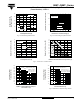
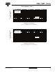
Fig. 1 - Current Ratings Characteristics Fig. 2 - Forward Voltage Drop Characteristics
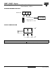
Fig. 3 - Total Power Loss Characteristics
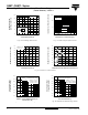
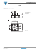
Fig. 4 - Maximum Non-Repetitive Surge Current Fig. 5 - Maximum Non-Repetitive Surge Current
030
Maximum Allowable
Case Temperature (°C)
Total Output Current (A)
5 101520
60
80
100
120
140
160
26MT.. Series
120° (rect.)
25
~
+
-
1
1.0 1.5 2.0 2.5 3.0 3.5 4.0
10
1000
Instantaneous Forward Current (A)
Instantaneous Forward Voltage (V)
26MT.. Series
T
J
= 25 °C
T
J
= 150 °C
Per junction
100
0 0.5
0 5 10 20 25
Total Output Current (A)
Maximum Total Power Loss (W)
0
10
20
30
40
55
26MT.. Series
T
J
= 150 °C
50
45
35
25
15
5
120° (rect.)
0 25 50 100 150
Maximum Allowable Ambient Temperature (°C)
Maximum Total Power Loss (W)
0
10
20
30
40
55
50
45
35
25
15
5
1 K/W
75 125
10 K/W
7 K/W
5 K/W
4 K/W
3 K/W
2 K/W
R
thSA
= 0.7 K/W - ΔR
1 10 100
Number of Equal Amplitude Half Cycle
Current Pulses (N)
Peak Half Sine Wave
Forward Current (A)
80
120
160
200
240
280
300
320
At any rated load condition and with
rated V
RRM
applied following surge.
at 60 Hz 0.0083 s
at 50 Hz 0.0100 s
Initial T
J
= 150 °C
26MT.. Series
260
220
180
140
100
0.01 0.1 1
Pulse Drain Duration (s)
Peak Half Sine Wave
Forward Current (A)
80
120
160
200
240
320
360
400
Maximum non-repetitive surge current
versus pulse train duration.
No voltage reapplied
Rated V
RRM
reapplied
Initial T
J
= 150 °C
26MT.. Series
280