
User Manual


Bulletin PD-20637 rev. A 12/06
70CRU04
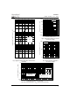
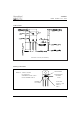
Fig. 1 - Typical Forward Voltage Drop Characteristics
(Per Diode)
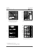
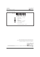
Fig. 4 - Max. Thermal Impedance Z
thJC
Characteristics (Per Diode)
Forward Voltage Drop - V
FM
(V)
Instantaneous Forward Current - I
F
(A)
Reverse Voltage - V
R
(V)
Reverse Voltage - V
R
(V)
Junction Capacitance - C
T
(pF)
t
1
, Rectangular Pulse Duration (Seconds)
Thermal Impedance Z
thJC
(°C/W)
Fig. 3 - Typical Junction Capacitance
Vs. Reverse Voltage
Reverse Current - I
R
( μA)
Fig. 2 - Typical Values Of Reverse Current
Vs. Reverse Voltage
10
100
1
000
1 10 100 1000
Tj = 25˚C
1
10
100
1
000
0 0.5 1 1.5 2 2.5 3
Tj = 175˚C
Tj = 125˚C
Tj = 25˚C
0
.01
0.1
1
10
0.0001 0.001 0.01 0.1 1 1
0
Single Pulse
(Thermal Resistance)
2
t
1
t
P
DM
Notes:
1. Duty factor D = t1/ t2
2. Peak Tj = Pdm x ZthJC + Tc
0
.001
0.01
0.1
1
10
100
1000
50 100 150 200 250 300 350 400
125˚C
25˚C
150˚C
Tj = 175˚C
Document Number: 93023
www.vishay.com
3