
Datasheet

BAT54, BAT54A, BAT54C, BAT54S
www.vishay.com
Vishay Semiconductors
Rev. 2.0, 02-Jun-17
1
Document Number: 85508
For technical questions within your region: DiodesAmericas@vishay.com
, DiodesAsia@vishay.com, DiodesEurope@vishay.com
THIS DOCUMENT IS SUBJECT TO CHANGE WITHOUT NOTICE. THE PRODUCTS DESCRIBED HEREIN AND THIS DOCUMENT
ARE SUBJECT TO SPECIFIC DISCLAIMERS, SET FORTH AT www.vishay.com/doc?91000
Small Signal Schottky Diodes, Single and Dual
DESIGN SUPPORT TOOLS click logo to get started
FEATURES
• These diodes feature very low turn-on voltage
and fast switching
• These devices are protected by a PN junction
guard ring against excessive voltage, such as
electrostatic discharges
• AEC-Q101 qualified available
• Base P/N-E3 - RoHS-compliant, commercial grade
• Base P/N-HE3 - RoHS-compliant, AEC-Q101 qualified
• Material categorization: for definitions of compliance
please see www.vishay.com/doc?99912
MECHANICAL DATA
Case: SOT-23
Weight: approx. 8.8 mg
Packaging codes/options:
18/10K per 13" reel (8 mm tape), 10K/box
08/3K per 7" reel (8 mm tape), 15K/box
Note
(1)
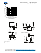
Device on fiberglass substrate, see layout on next page
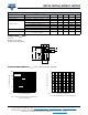
Top View
Top View
BAT54
BAT54C
BAT54A
BAT54S
1
3
1
3
1
3
1
2
2
2
2
3
Available
Models
PARTS TABLE
PART ORDERING CODE CIRCUIT CONFIGURATION TYPE MARKING REMARKS
BAT54
BAT54-E3-08 or BAT54-E3-18
Single L4
Tape and reel
BAT54-HE3-08 or BAT54-HE3-18
BAT54A
BAT54A-E3-08 or BAT54A-E3-18
Common anode L42
BAT54A-HE3-08 or BAT54A-HE3-18
BAT54C
BAT54C-E3-08 or BAT54C-E3-18
Common cathode L43
BAT54C-HE3-08 or BAT54C-HE3-18
BAT54S
BAT54S-E3-08 or BAT54S-E3-18
Dual serial L44
BAT54S-HE3-08 or BAT54S-HE3-18
ABSOLUTE MAXIMUM RATINGS (T
amb
= 25 °C, unless otherwise specified)
PARAMETER TEST CONDITION SYMBOL VALUE UNIT
Repetitive peak reverse voltage V
RRM
30 V
Forward continuous current
(1)
I
F
200 mA
Repetitive peak forward current
(1)
I
FRM
300 mA
Surge forward current
(1)
t
p
< 1 s I
FSM
600 mA
Power dissipation P
tot
230 mW
THERMAL CHARACTERISTICS (T
amb
= 25 °C, unless otherwise specified)
PARAMETER TEST CONDITION SYMBOL VALUE UNIT
Thermal resistance junction to ambient air
Device on fiberglass substrate,
see layout on next page
R
thJA
430 K/W
Junction temperature T
j
125 °C
Storage temperature range T
stg
-65 to +150 °C
Operating temperature range T
op
-55 to +125 °C