
Datasheet

BYS12-90-M3
www.vishay.com
Vishay General Semiconductor
Revision: 09-May-2019
2
Document Number: 89412
For technical questions within your region: DiodesAmericas@vishay.com
, DiodesAsia@vishay.com, DiodesEurope@vishay.com
THIS DOCUMENT IS SUBJECT TO CHANGE WITHOUT NOTICE. THE PRODUCTS DESCRIBED HEREIN AND THIS DOCUMENT
ARE SUBJECT TO SPECIFIC DISCLAIMERS, SET FORTH AT www.vishay.com/doc?91000
Note
(1)
Pulse test: 300 μs pulse width, 1 % duty cycle
Notes
(1)
Mounted on epoxy-glass hard tissue
(2)
Mounted on epoxy-glass hard tissue, 50 mm
2
35 μm Cu
(3)
Mounted on Al-oxide-ceramic (Al
2
O
3
), 50 mm
2
35 μm Cu
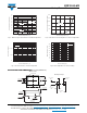
RATINGS AND CHARACTERISTICS CURVES (T
A
= 25 °C unless otherwise noted)
Fig. 1 - Forward Current vs. Forward Voltage Fig. 2 - Max. Average Forward Current vs. Ambient Temperature
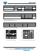
ELECTRICAL CHARACTERISTICS (T
A
= 25 °C unless otherwise noted)
PARAMETER TEST CONDITIONS SYMBOL BYS12-90 UNIT
Maximum instantaneous forward voltage
I
F
= 1.0 A
T
J
= 25 °C V
F
(1)
750
mV
I
F
= 15 mA 360
Maximum DC reverse current V
RRM
T
J
= 25 °C
I
R
(1)
100 μA
T
J
= 100 °C 1 mA
THERMAL CHARACTERISTICS (T
A
= 25 °C unless otherwise noted)
PARAMETER SYMBOL BYS12-90 UNIT
Maximum thermal resistance, junction to lead R
JL
25 °C/W
Maximum thermal resistance, junction to ambient
R
JA
(1)
150
°C/WR
JA
(2)
125
R
JA
(3)
100
ORDERING INFORMATION (Example)
PREFERRED P/N UNIT WEIGHT (g) PREFERRED PACKAGE CODE BASE QUANTITY DELIVERY MODE
BYS12-90-M3/TR 0.064 TR 1800 7" diameter plastic tape and reel
BYS12-90-M3/TR3 0.064 TR3 7500 13" diameter plastic tape and reel
10
1
0.1
0 0.2 0.4 0.6 0.8 1.0 1.2
Instantaneous Forward Voltage (V)
Instantaneous Forward Current (A)
T
J
= 150 °C
T
J
= 125 °C
T
J
= 25 °C
0
0.2
0.4
0.6
0.8
1.0
1.2
1.4
1.6
0 20 40 60 80 100 120 140 160
R
thJA
≤ K/W
V
R
= V
RRM
Half Sine-Wave
Ambient Temperature (°C)
Average Forward Current (A)