
Datasheet

CMB 0207
www.vishay.com
Vishay Beyschlag
Revision: 11-Feb-16
9
Document Number: 28755
For technical questions, contact: melf@vishay.com
THIS DOCUMENT IS SUBJECT TO CHANGE WITHOUT NOTICE. THE PRODUCTS DESCRIBED HEREIN AND THIS DOCUMENT
ARE SUBJECT TO SPECIFIC DISCLAIMERS, SET FORTH AT www.vishay.com/doc?91000
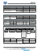
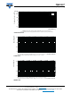
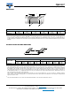
DIMENSIONS
Note
• Color code marking is applied according to IEC 60062
(1)
in four bands (E24 series) or five bands (E96 series). Each color band appears as
a single solid line, voids are permissible if at least
2
/
3
of the band is visible from each radial angle of view. The last color band for tolerance
is approximately 50 % wider than the other bands. An interrupted brown band between the 2
nd
and 3
rd
full band indicates the special carbon
film type.
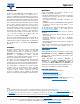
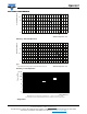
PATTERN STYLES FOR MELF RESISTORS
Notes
• The rated dissipation applies only if the permitted film temperature is not exceeded. Furthermore, a high level of ambient temperature or of
power dissipation may raise the temperature of the solder joint, hence special solder alloys or board materials may be required to maintain
the reliability of the assembly. Specified power rating above 125 °C requires dedicated heat-sink pads, which to a great extend depend
onboard materials and design. The given solder pad dimensions reflect the considerations for board design and assembly as outlined e.g.
in standards IEC 61188-5-x
(1)
, or in publication IPC-7351. They do not guarantee any supposed thermal properties, particularly as these are
also strongly influenced by many other parameters.
Still, the given solder pad dimensions will be found adequate for most general applications, e.g. those referring to “standard operation
mode”. Please note however that applications for “power operation mode” require special considerations for the design of solder pads and
adjacent conductor areas.
(1)
The quoted IEC standards are also released as EN standards with the same number and identical contents.
DIMENSIONS AND MASS
TYPE / SIZE
L
(mm)
D
(mm)
L
1
MIN.
(mm)
D
1
(mm)
K
(mm)
MASS
(mg)
CMB 0207 5.8 + 0/- 0.15 2.2 + 0/- 0.2 3.2 D + 0/- 0.2 1.1 ± 0.1 79
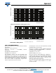
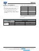
RECOMMENDED SOLDER PAD DIMENSIONS
TYPE / SIZE
WAVE SOLDERING REFLOW SOLDERING
G
(mm)
Y
(mm)
X
(mm)
Z
(mm)
G
(mm)
Y
(mm)
X
(mm)
Z
(mm)
CMB 0207 2.8 2.1 2.6 7.0 3.2 1.7 2.4 6.6
L
1
K
D
1
D
L
G
X
Y
Z