
Datasheet

CNY17F
www.vishay.com
Vishay Semiconductors
Rev. 2.2, 08-Jan-14
4
Document Number: 83607
For technical questions, contact: optocoupleranswers@vishay.com
THIS DOCUMENT IS SUBJECT TO CHANGE WITHOUT NOTICE. THE PRODUCTS DESCRIBED HEREIN AND THIS DOCUMENT
ARE SUBJECT TO SPECIFIC DISCLAIMERS, SET FORTH AT www.vishay.com/doc?91000
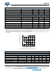
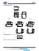
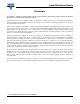
Fig. 2 - Test Circuit, Non-Saturated Operation
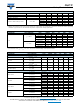
Fig. 3 - Test Circuit, Saturated Operation
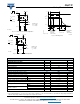
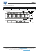
Fig. 4 - Switching Times
Note
• As per DIN EN 60747-5-5, § 7.4.3.8.2, this optocoupler is suitable for “safe electrical insulation” only within the safety ratings. Compliance
with the safety ratings shall be ensured by means of protective circuits.
Channel I
Channel II
95 10804-3
R
G
= 50 Ω
t
p
t
p
= 50 µs
T
= 0.01
+ 5 V
I
F
0
50 Ω R
L
I
F
Oscilloscope
R
L
= 1 MΩ
C
L
= 20 pF
Channel I
Channel II
95 10843
R
G
= 50 Ω
t
p
t
p
= 50 µs
T
= 0.01
+ 5 V
I
C
I
F
0
50 Ω
1 kΩ
I
F
= 10 mA
Oscilloscope
R
L
≥
C
L
20 pF
1 MΩ
≤
t
p
t
t
0
0
10 %
90 %
100 %
t
r
t
d
t
on
t
s
t
f
t
off
I
F
I
C
t
p
Pulse duration
t
d
Delay time
t
r
Rise time
t
on
(= t
d
+ t
r
) Turn-on time
t
s
Storage time
t
f
Fall time
t
off
(= t
s
+ t
f
) Turn-off time
96 11698
SAFETY AND INSULATION RATINGS
PARAMETER SYMBOL VALUE UNIT
MAXIMUM SAFETY RATINGS
Output safety power P
SO
700 mW
Input safety current I
SI
400 mA
Safety temperature T
SI
175 °C
Comparative tracking index CTI 175
INSULATION RATED PARAMETERS
Maximum withstanding isolation voltage V
ISO
5000 V
RMS
Maximum transient isolation voltage V
IOTM
8000 V
peak
Maximum repetitive peak isolation voltage V
IORM
890 V
peak
Insulation resistance T
amb
= 25 °C, V
DC
= 500 V R
IO
≥ 10
12
Ω
Isolation resistance T
amb
= 100 °C, V
DC
= 500 V R
IO
≥ 10
11
Ω
Climatic classification (according to IEC 68 part 1) 55/115/21
Environment (pollution degree in accordance to DIN VDE 0109) 2
Creepage distance
Standard DIP-4 ≥ 7mm
SMD ≥ 7mm
Clearance distance
Standard DIP-4 ≥ 8mm
SMD ≥ 8mm
Insulation thickness DTI ≥ 0.4 mm