
Owner manual


Document Number: 93085 For technical questions, contact: diodes-tech@vishay.com
www.vishay.com
Revision: 30-Jul-08 5
HFA25TB60
HEXFRED
®
Ultrafast Soft Recovery Diode, 25 A
Vishay High Power Products
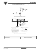
Fig. 9 - Reverse Recovery Parameter Test Circuit
Fig. 10 - Reverse Recovery Waveform and Definitions
IRFP250
D.U.T.
L = 70 µH
V
R
= 200 V
0.01 Ω
G
D
S
dI
F
/dt
adjust
Q
rr
0.5 I
RRM
dI
(rec)M
/dt
0.75 I
RRM
I
RRM
t
rr
t
b
t
a
I
F
dI
F
/dt
0
(1)
(2)
(3)
(4)
(5)
(1) dI
F
/dt - rate of change of current
through zero crossing
(2) I
RRM
- peak reverse recovery current
(3) t
rr
- reverse recovery time measured
from zero crossing point of negative
going I
F
to point where a line passing
through 0.75 I
RRM
and 0.50 I
RRM
extrapolated to zero current.
(4) Q
rr
- area under curve defined by t
rr
and I
RRM
t
rr
x I
RRM
2
Q
rr
=
(5) dI
(rec)M
/dt - peak rate of change of
current during t
b
portion of t
rr
LINKS TO RELATED DOCUMENTS
Dimensions http://www.vishay.com/doc?95221
Part marking information http://www.vishay.com/doc?95224