
Datasheet

HVR25, HVR37
www.vishay.com
Vishay BCcomponents
Revision: 11-Jul-2018
1
Document Number: 30260
For technical questions, contact: filmresistorsleaded@vishay.com
THIS DOCUMENT IS SUBJECT TO CHANGE WITHOUT NOTICE. THE PRODUCTS DESCRIBED HEREIN AND THIS DOCUMENT
ARE SUBJECT TO SPECIFIC DISCLAIMERS, SET FORTH AT www.vishay.com/doc?91000
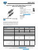
High Ohmic (up to 10 M)/High Voltage (up to 3.5 kV)
Metal Film Leaded Resistors
DESIGN SUPPORT TOOLS
A homogenous film of metal alloy is deposited on a high
grade ceramic body. After a helical groove has been cut in
the resistive layer, tinned electrolytic copper wires are
welded to the end-caps. The resistors are coated with a
blue, non-flammable lacquer, which provides electrical,
mechanical, and climatic protection.
FEATURES
• Technology: metal film
• High pulse loading (up to 10 kV) capability
• Small size (0207/0411)
• Compatible with lead (Pb)-free and lead
containing soldering processes
• Material categorization: for definitions of compliance
please see www.vishay.com/doc?99912
APPLICATIONS
• Power supplies
• Electronic ballast
• White goods
• Television
click logo to get started
Available
Models
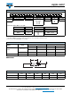
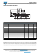
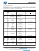
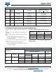
TECHNICAL SPECIFICATIONS
DESCRIPTION HVR25 HVR37
Resistance range 100 k to 10 M 100 k to 10 M
Resistance tolerance ± 5 % ± 1 % ± 5 % ± 1 %
E-series E24 series E24/E96 series E24 series E24/E96 series
Temperature coefficient 200 ppm/K
Climatic category (LCT/UCT/days) 55/155/56
Rated dissipation, P
70
0.25 W 0.5 W
Maximum permissible voltage U
max.
DC 1600 V 3500 V
RMS 1150 V 2500 V
Basic specification IEC 60115-1
Stability after:
Load (1000 h, P
70
)± (5 % R + 0.1 ± (1.5 % R + 0.1 ± (5 % R + 0.1 ± (1.5 % R + 0.1
Long term damp heat test (56 days) ± (1.5 % R + 0.1 ± (1.5 % R + 0.1 ± (1.5 % R + 0.1 ± (1.5 % R + 0.1
Soldering (10 s, 260 °C) ± (1 % R + 0.1 ± (1 % R + 0.1 ± (1 % R + 0.1 ± (1 % R + 0.1