
Datasheet

HVR25, HVR37
www.vishay.com
Vishay BCcomponents
Revision: 11-Jul-2018
3
Document Number: 30260
For technical questions, contact: filmresistorsleaded@vishay.com
THIS DOCUMENT IS SUBJECT TO CHANGE WITHOUT NOTICE. THE PRODUCTS DESCRIBED HEREIN AND THIS DOCUMENT
ARE SUBJECT TO SPECIFIC DISCLAIMERS, SET FORTH AT www.vishay.com/doc?91000
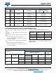
PRODUCTS WITH RADIAL LEADS (HVR25)
Note
• Please refer document number 28721 “Packaging” for more detail
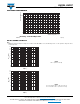
MARKING
The nominal resistance and tolerance are marked on the resistor using four or five colored bands in accordance with IEC 60062,
marking codes for resistors and capacitors. Standard values of nominal resistance are taken from the E24 and E24/E96 series
for resistors with a tolerance of 5 % or 1 % respectively. The values of the E24/E96 series are in accordance with IEC 60063.
Yellow and grey are used instead of gold and silver because metal particles in the lacquer could affect high-voltage properties.
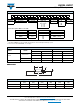
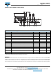
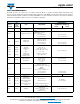
DIMENSIONS - Radial taping
SYMBOL PARAMETER VALUE TOLERANCE UNIT
P Pitch of components 12.7 1.0 mm
P
0
Feed-hole pitch 12.7 0.2 mm
P
1
Feed-hole centre to lead at topside at the tape 3.85 0.5 mm
P
2
Feed-hole center to body center 6.35 1.0 mm
F Lead-to-lead distance 4.8 0.7/-0 mm
W Tape width 18.0 0.5 mm
W
0
Minimum hold down tape width 5.5 - mm
H1 Component height 29 Max. mm
H
0
Lead wire clinch height 16.5 0.5 mm
H Height of component from tape center 19.5 1mm
D
0
Feed-hole diameter 4.0 0.2 mm
L Maximum length of snipped lead 11.0 - mm
L
1
Minimum lead wire (tape portion) shortest lead 2.5 - mm
P
P
2
W
W
0
D
0
P
1
P
0
L
1
L
F
H
0
H
1
H