
Datasheet

IL420, IL4208
www.vishay.com
Vishay Semiconductors
Rev. 2.1, 11-Jun-13
3
Document Number: 83629
For technical questions, contact: optocoupleranswers@vishay.com
THIS DOCUMENT IS SUBJECT TO CHANGE WITHOUT NOTICE. THE PRODUCTS DESCRIBED HEREIN AND THIS DOCUMENT
ARE SUBJECT TO SPECIFIC DISCLAIMERS, SET FORTH AT www.vishay.com/doc?91000
Note
• Minimum and maximum values are testing requirements. Typical values are characteristics of the device and are the result of engineering
evaluation. Typical values are for information only and are not part of the testing requirements.
Note
• As per IEC60747-5-2, § 7.4.3.8.1, this optocoupler is suitable for “safe electrical insulation” only within the safety ratings. Compliance with
the safety ratings shall be ensured by means of protective circuits.
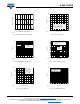
TYPICAL CHARACTERISTICS (T
amb
= 25 °C, unless otherwise specified)
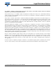
Fig. 1 - Forward Voltage vs. Forward Current Fig. 2 - Peak LED Current vs. Duty Factor,
COUPLER
Critical rate of rise of coupled
input/output voltage
I
T
= 0 A, V
RM
= V
DM
= V
DRM
dV/dt 5000 V/μs
Capacitance (input to output) f = 1 MHz, V
IO
= 0 V C
IO
0.8 pF
SWITCHING CHARACTERISTICS (T
amb
= 25 °C, unless otherwise specified)
PARAMETER TEST CONDITION SYMBOL MIN. TYP. MAX. UNIT
Turn-on time V
RM
= V
DM
= V
DRM
t
on
35 μs
SAFETY AND INSULATION RATINGS (T
amb
= 25 °C, unless otherwise specified)
PARAMETER TEST CONDITION SYMBOL MIN. TYP. MAX. UNIT
Climatic classification
(according to IEC68 part 1)
55/100/21
Comparative tracking index CTI 175 399
V
IOTM
8000 V
V
IORM
630 V
P
SO
500 mW
I
SI
250 mA
T
SI
175 °C
Creepage distance Standard DIP-8 7 mm
Clearance distance Standard DIP-8 7 mm
Creepage distance 400 mil DIP-8 8 mm
Clearance distance 400 mil DIP-8 8 mm
Insulation thickness For IL4208 only 0.4 mm
ELECTRICAL CHARACTERISTICS (T
amb
= 25 °C, unless otherwise specified)
PARAMETER TEST CONDITION SYMBOL MIN. TYP. MAX. UNIT
iil420_01
1001010.1
0.7
0.8
0.9
1.0
1.1
1.2
1.3
1.4
I
F
- Forward Current (mA)
V
F
- Forward Voltage (V)
T
amb
= - 55 °C
T
amb
= 25 °C
T
amb
= 85 °C
iil420_02
10
-6
10
-5
10
-4
10
-3
10
-2
10
-1
10
0
10
1
10
100
100
0
10 000
t- LED Pulse Duration (s)
I
F(pk)
- Peak LED Current (mA)
0.005
0.05
0.02
0.01
0.1
0.2
0.5
Duty factor
t
τ
DF = /t
τ