
Datasheet

www.vishay.com For technical questions, contact: sfer@vishay.com Document Number: 50054
68 Revision: 27-Oct-10
LPS 800
Vishay Sfernice
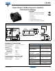
Power Resistor for Mounting onto a Heatsink
Thick Film Technology
RECOMMENDATIONS FOR MOUNTING ONTO A HEATSINK
• Surfaces in contact must be carefully cleaned.
• The heatsink must have an acceptable flatness: From 0.05 mm to 0.1 mm/100 mm.
• Roughness of the heatsink must be around 6.3 µm. In order to improve thermal conductivity, surfaces in contact (alumina,
heatsink) should be coated with a silicone grease (type SI 340 from Rhône-Poulenc or Dow 340 from Dow Corning) or a thermal
film (type Q Pad II) easier and faster to install than the grease.
• The fastening of the resistor to the heatsink is under pressure control of two screws tightened at 2 Nm for full power availability.
• The following accessories are supplied with each product: 2 screws CHC M4 * 25 class 8.8 and 2 M4 contact lock washers for
heatsink mounting,
2 screws TH M4 * 6/6 and 2 M4 contact lock washers for
connections.
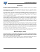
CHOICE OF THE HEATSINK
The user must choose the heatsink according to the working conditions of the component (power, room temperature). Maximum
working temperature must not exceed 175 °C. The dissipated power is simply calculated by the following ratio:
P: Expressed in W
ΔT: Difference between maximum working temperature and room temperature
R
TH (j - c)
: Thermal resistance value measured between resistive layer and outer side of the resistor. It is the thermal
resistance of the component: (see specifications environmental paragraph).
R
TH (c - a)
: Thermal resistance value measured between outer side of the resistor and room temperature. It is the thermal
resistance of the thermal interface, the heatsink (type, shape) and the quality of the fastening device.
Example:
R
TH (c - a)
for LPS 800 power dissipation 180 W at + 50 °C room temperature.
ΔT ≤ 175 °C - 50 °C = 125 °C
R
TH (j - c)
+ R
TH (c - a)
= = = 0.69 °C/W
R
TH (j - c)
= 0.112 °C/W
R
TH (c - a)
= 0.69 °C/W - 0.112 °C/W = 0.578 °C/W
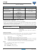
PERFORMANCE
TESTS CONDITIONS REQUIREMENTS
Momentary Overload
IEC 60115-1
1.5 x P
r
/10 s
U
max.
≤ U
L
= 5000 V
± (0.25 % + 0.05 Ω)
Rapid Temperature Change
IEC 60115-1/IEC 60068-2-14 Test Na
50 cycles
- 55 °C to + 175 °C
± (0.5 % + 0.05 Ω)
Load Life
IEC 60115-1
1000 h (90/30) P
r
at 85 °C
± (0.5 % + 0.05 Ω)
Humidity (Steady State)
IEC 60115-1
56 days RH 95 %/40 °C
± (0.5 % + 0.05 Ω)
Vibration
MIL STD 202 Method 204 Cond. D
(10 g; 5/500 Hz)
± (0.25 % + 0.05 Ω)
Climatic Sequence
IEC 60115-1
(55/175/56)
± (1 % + 0.05 Ω)
Tightening Torque on Heatsink
LPS 800
2 Nm
P
ΔT
R
TH (j - c)
R
TH (c - a)
+[]
----------------------------------------------------------
=
ΔT
P
-------
125
180
----------