
Datasheet

021 ASM
Vishay BCcomponents
Aluminum Capacitors
Axial Standard Miniature
www.vishay.com For technical questions, contact: aluminumcaps1@vishay.com
Document Number: 28325
174 Revision: 06-Sep-10
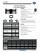
Table 1
Note
Detailed tape dimensions see section ‘PACKAGING’.
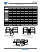
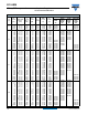
Table 2
AXIAL; DIMENSIONS in millimeters, MASS AND PACKAGING QUANTITIES
NOMINAL
CASE SIZE
Ø D x L
CASE
CODE
AXIAL: FORM AA, BA, and BR
MASS
(g)
PACKAGING QUANTITIES
ØdI
ØD
max.
L
max.
F
min.
FORM
AA
FORM
BA
FORM
BR
4.5 x 10 2 0.6 - 5.0 10.5 15 0.5 - 1000 3000
6 x 10 3 0.6 - 6.3 10.5 15 0.7 - 1000 1000
8 x 11 5a 0.6 - 8.5 11.5 15 1.1 - 500 500
6.5 x 18 4 0.8 - 6.9 18.5 25 1.3 - 1000 1000
8 x 18 5 0.8 - 8.5 18.5 25 1.7 - 500 500
10 x 18 6 0.8 - 10.5 18.5 25 2.5 - 500 500
10 x 25 7 0.8 - 10.5 25.5 30 3.3 - 500 500
10 x 30 00 0.8 55 ± 1 10.5 30.5 35 4.8 340 - 500
12.5 x 30 01 0.8 55 ± 1 13.0 30.5 35 7.4 260 - 400
15 x 30 02 0.8 55 ± 1 15.5 30.5 35 11.7 200 - 250
18 x 30 03 0.8 55 ± 1 18.5 30.5 35 12.9 120 - -
18 x 38 04 0.8 34 ± 1 18.5 39.5 44 19.0 125 - -
21 x 38 05 0.8 34 ± 1 21.5 39.5 44 24.0 100 - -
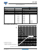
90° ± 2°
(3 x)
3.6
+ 0.03
- 0.1
+ 0.2
- 0.4
1.05
(3 x)
0
- 0.05
1.3
(3 x)
D3
120°
(3 x)
1.3
+ 0.1
0
(3 x)
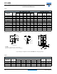
Mounting holes
Form MR:
Case Ø D x L = 15 mm x 30 mm to 21 mm x 38 mm
Especially for applications with severe shocks and vibrations
Fig.5 Mounting hole diagramm and outline. Form MR: with mounting ring and pins
Ø d1
D
L
Ø D2
1
+ 1.0
- 0.5
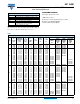
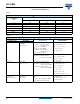
MOUNTING RING; DIMENSIONS in millimeters, MASS AND PACKAGING QUANTITIES
NOMINAL
CASE SIZE
Ø D x L
CASE
CODE
MOUNTING RING: FORM MR
MASS
(g)
PACKAGING
QUANTITIES
Ø d1 Ød2
ØD2
max.
D3
L
max.
15 x 30 02 0.8 1.0 + 0.4 17.5 16.5 ± 0.2 33 11.7 200
18 x 30 03 0.8 1.0 + 0.4 19.5 18.5 ± 0.2 33 12.9 240
18 x 38 04 0.8 1.0 + 0.4 19.5 18.5 ± 0.2 42 19.0 100
21 x 38 05 0.8 1.0 + 0.4 22.5 21.5 ± 0.2 42 24.0 100