
Datasheet
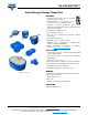

196 HVC ENYCAP™
www.vishay.com
Vishay BCcomponents
Revision: 23-Jul-2018
10
Document Number: 28409
For technical questions, contact: hybridstorage@vishay.com
THIS DOCUMENT IS SUBJECT TO CHANGE WITHOUT NOTICE. THE PRODUCTS DESCRIBED HEREIN AND THIS DOCUMENT
ARE SUBJECT TO SPECIFIC DISCLAIMERS, SET FORTH AT www.vishay.com/doc?91000
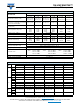
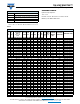
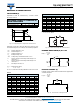
Fig. 19 - Typical Leakage Current at 20 °C as a Function of Time
Table 5
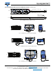
DISCHARGE CHARACTERISTICS
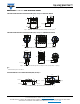
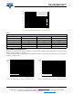
Backup time of 196 HVC series capacitors depends on minimum memory holding voltage and discharge current (corresponding
with the current consumption of the load).
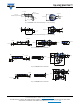
For minimum backup times of standard and vertical miniaturized series see Fig. 20 to Fig. 23 (charging time 24 h and CC-CV
charging according to table 3).
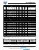
Fig. 20 - Typical Backup Time as a Function of Discharge Current Fig. 21 - Typical Backup Time as a Function of Discharge Current
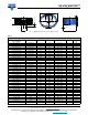
VOLTAGE TO BE USED FOR SERIES CONNECTION
N CELLS IN SERIES U
R
(V) U
1
(V) U
2
(V)
1 1.4 1.3 0.7
2 2.8 2.7 1.9
3 4.2 4.0 3.1
4 5.6 5.4 4.4
5 7.0 6.7 5.6
6 8.4 8.1 6.9
1
10
100
1000
10 000
100 000
0 1020304050607080
I
L
(μA)
Time (h)
3
2
1
4
Curve 1: 90 F (1.4 V to 8.4 V)
Curve 2: 45 F (2.8 V to 5.6 V)
Curve 3: 15 F (1.4 V to 8.4 V)
Curve 4: 4 F (1.4 V to 8.4 V)
0.1 1 10 100
Discharge current (mA)
C = 4 F (1.4 V to 8.4 V)
10
10
2
Backup
time
(s)
1
10
3
10
4
10
5
10
10
2
0.1 1 10
Backup
time
(s)
Discharge current (mA)
1
10
3
10
4
10
5
10
6
100
C = 15 F (1.4 V to 8.4 V)