
Datasheet


196 HVC ENYCAP™
www.vishay.com
Vishay BCcomponents
Revision: 23-Jul-2018
13
Document Number: 28409
For technical questions, contact: hybridstorage@vishay.com
THIS DOCUMENT IS SUBJECT TO CHANGE WITHOUT NOTICE. THE PRODUCTS DESCRIBED HEREIN AND THIS DOCUMENT
ARE SUBJECT TO SPECIFIC DISCLAIMERS, SET FORTH AT www.vishay.com/doc?91000
PRODUCT AND MOUNTING CHARACTERISTICS
Attention: parts are pre-charged at delivery - handle appropriate.
At delivery products are pre-charged and voltage over terminals is near nominal voltage. Short circuiting of product terminals
is permitted. Do not short circuit permanently. Short circuiting of charged cells may heat up the cells.
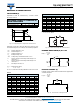
For printed circuit board mounting it has to be taken into account, that for certain form factors top and bottom of products may
not be insulated.
Capacitor disposal methods should be in accordance with local and state regulations.
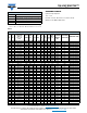
Table 6.1
Notes
(1)
n... number of cells
(2)
R
I
equals ESR
AC
or ESR
DC
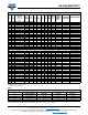
Table 6.2: Stacked Through Hole configuration (STH), Surface Mount Flat configuration (SMF), and Lay Flat
configuration with Connector
Notes
• Robustness - bending limited to ± 15°, force in direction of tab / pin, no twisting allowed
• Solder bath test: max. allowed case temperature during test is e.g. 85 °C or immersion of one (1) pad only
• Wave soldering allowed
(1)
R
I
equals ESR
AC
or ESR
DC
TEST PROCEDURES AND REQUIREMENTS
NAME OF TEST
ENYCAP
TESTS
SUBCLAUSE
PROCEDURE
(quick reference)
REQUIREMENTS
(2)
Damp heat, steady state 4.12 500 h at 55 °C; RH 90 % to 95 %; no voltage applied
C/C: ± 30 %
R
I
4 x spec. limit
I
L
2 x spec. limit
Endurance 4.13.1
T
amb
= 70 °C / 85 °C; rated voltage U
R
applied;
4.0 F, 15 F: 1000 h
45 F, 90 F: 2000 h
C/C: ± 30 %
R
I
4 x spec. limit
I
L
2 x spec. limit
Useful life 4.13.2
T
amb
= 70 °C / 85 °C; rated voltage U
R
applied;
4.0 F, 15 F: 1000 h
45 F, 90 F: 2000 h
C/C: ± 30 %
R
I
4 x spec. limit
I
L
2 x spec. limit
Storage at upper category
temperature
4.17
T
amb
= 70 °C / 85 °C; no voltage applied;
1000 h
C/C: ± 30 %
R
I
4 x spec. limit
I
L
2 x spec. limit
Self discharge 4.1.5
24 h storage at room temperature after application
of U
R
for 1 h
Remaining voltage: (U
R
x 0.9)
Characteristics at high and
low temperature
4.19
Step 1: reference measurement at 20 °C of C, R
I
, and I
L
Step 2: measurement at -20 °C
Step 3: measurement at +20 °C
Step 4: measurement at +70 °C
Step 5: measurement at +20 °C
C/C: ± 30 % of +20 °C value
R
I
5 x the +20 °C value
I
L
4 x the +20 °C value
Surge voltage 4.15
Max. 30 s at room temperature
U
S
= n
(1)
x 1.6 V
No change of parameter!
After surge voltage, discharge
product below rated voltage
TEST PROCEDURES AND REQUIREMENTS
NAME OF TEST
ENYCAP
TESTS
SUBCLAUSE
PROCEDURE
(quick reference)
REQUIREMENTS
(1)
Robustness of terminations 4.4
Tensile strength; application of load force in pin / tab
direction for 10 s:
10 N: for product size Ø 8 mm
5 N: for product size Ø < 8 mm
No breaks
Resistance to soldering heat 4.5 260 °C; 5 s
C/C: ± 10 %
R
I
and I
L
spec. limit
Solderability 4.6 Solder bath; 236 °C; 2 s; one pin immersed 75 % tinning
Vibration 4.8
10 Hz to 55 Hz; 1.5 mm; 3 directions;
2 h per direction
C/C: ± 10 %
R
I
and I
L
spec. limit