
Datasheet

196 HVC ENYCAP™
www.vishay.com
Vishay BCcomponents
Revision: 23-Jul-2018
9
Document Number: 28409
For technical questions, contact: hybridstorage@vishay.com
THIS DOCUMENT IS SUBJECT TO CHANGE WITHOUT NOTICE. THE PRODUCTS DESCRIBED HEREIN AND THIS DOCUMENT
ARE SUBJECT TO SPECIFIC DISCLAIMERS, SET FORTH AT www.vishay.com/doc?91000
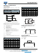
MEASURING OF CHARACTERISTICS
CAPACITANCE (C)
Capacitance shall be measured by constant current
discharge method.
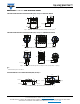
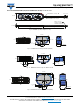
Fig. 15 - Voltage Diagram for Capacitance Measurement
Capacitance value C
R
is given by discharge current I
D
, time
t and rated voltage U
R
, according to the following equation:
For I
D
, U
1
, and U
2
the following definitions have to be used:
Table 4
Note
•For U
2
see also Table 5
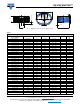
Fig. 16 - Test Circuit for Capacitance Measurement
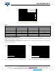
INTERNAL RESISTANCE (R
I
) AT 1 kHz
Fig. 17 - Test Circuit for R
I
Measurement
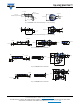
LEAKAGE CURRENT (I
L
)
Leakage current shall be measured after 30 min application
of rated voltage U
R
:
Fig. 18 - Test Circuit for Leakage Current
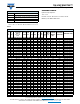
DISCHARGE CURRENT AS A FUNCTION OF
RATED CAPACITANCE
PARAMETER VALUE UNIT
Rated capacitance, C
R
4 154590 F
Discharge current, I
D
4 154590mA
C
R
Rated capacitance, in F
U
R
Rated voltage, in V
U
1
Starting voltage, in V
U
2
Ending voltage, in V
U
3
Voltage drop at internal resistance, in V
t
1
Time from start of discharge until voltage U
1
is
reached, in s
t
2
Time from start of discharge until voltage U
2
is
reached, in s
I
D
Discharge current, in A
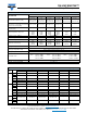
CAPACITANCE
C (F) I
D
(A) U
R
(V) U
1
(V) U
2
(V) t
1
(s) t
2
(s)
4 0.004 1.4 1.3 0.7 5 > 600
4 0.004 2.8 2.7 1.9 5 > 600
4 0.004 4.2 4.0 3.1 5 > 600
4 0.004 5.6 5.4 4.4 5 > 600
4 0.004 7.0 6.7 5.6 5 > 600
4 0.004 8.4 8.1 6.9 5 > 600
15 0.015 1.4 1.3 0.7 5 > 600
15 0.015 2.8 2.7 1.9 5 > 600
15 0.015 4.2 4.0 3.1 5 > 600
15 0.015 5.6 5.4 4.4 5 > 600
15 0.015 7.0 6.7 5.6 5 > 600
15 0.015 8.4 8.1 6.9 5 > 600
U
R
U
1
U
2
t
1
t
2
ΔU
3
(s)
30 min
C
R
F
I
D
A x t
2
s - t
1
s
U
1
V - U
2
V
----------------------------------------------------------
=
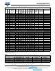
45 0.045 1.4 1.3 0.7 5 > 600
45 0.045 2.8 2.7 1.9 5 > 600
45 0.045 4.2 4.0 3.1 5 > 600
45 0.045 5.6 5.4 4.4 5 > 600
90 0.090 1.4 1.3 0.7 5 > 600
90 0.090 2.8 2.7 1.9 5 > 600
90 0.090 4.2 4.0 3.1 5 > 600
90 0.090 5.6 5.4 4.4 5 > 600
90 0.090 7.0 6.7 5.6 5 > 600
90 0.090 8.4 8.1 6.9 5 > 600
CAPACITANCE
C (F) I
D
(A) U
R
(V) U
1
(V) U
2
(V) t
1
(s) t
2
(s)
A
V C
Constant
current
discharger
+
R
I
U
C
V
10
-3
----------------
=
V
A
1 mA
C
1 kHz
+
I
L
A
U
S
V
10
-4
----------------
=
V
R
S
100 Ω
C
++