
Datasheet

196 HVC ENYCAP™
www.vishay.com
Vishay BCcomponents
Revision: 23-Jul-2018
3
Document Number: 28409
For technical questions, contact: hybridstorage@vishay.com
THIS DOCUMENT IS SUBJECT TO CHANGE WITHOUT NOTICE. THE PRODUCTS DESCRIBED HEREIN AND THIS DOCUMENT
ARE SUBJECT TO SPECIFIC DISCLAIMERS, SET FORTH AT www.vishay.com/doc?91000
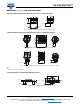
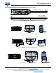
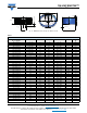
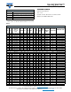
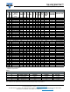
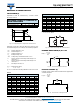
DIMENSIONS in millimeters AND AVAILABLE FORMS
STACKED THROUGH HOLE CONFIGURATION (STH): Examples VERTICAL MOUNT
Fig. 1 - Form A2: Stacked Through Hole (example 4 cells, 2 pins)
(1)
STACKED THROUGH HOLE CONFIGURATION (STH): Examples HORIZONTAL MOUNT
Fig. 2 - Form B2: Stacked Through Hole (example 5 cells, 2 pins)
(1)
Fig. 3 - Form B3: Stacked Through Hole (example 4 cells, keyed polarity - 3 pins)
(1)
Note
(1)
Bottom and top are not isolated
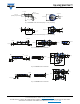
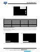
SURFACE MOUNT FLAT CONFIGURATION (SMF): Examples
Fig. 4 - Form C: Surface Mount Flat (single cell, keyed polarity)
L
max.
Ø D
max.
F
+
+
-
-
-
Ø 0.8
Ø 0.64
6 (2 x)
+ 0.5
- 0.5
L
max.
Ø D
max.
F
+
-
Ø 0.64
3.5 (2 x)
+ 0.5
- 0.5
L
max.
FØ 0.64 (3 x)
F
1
+
-
Ø D
max.
3.5 (3 x)
+ 0.5
- 0.5
3 (2 x)
0.1 (2 x)
0.5 (2 x)
3.8 max.
1
3.5 (2 x)
+ 0.5
- 0.5
4 (2 x)
+ 0.5
- 0.5
L
max.
Ø D
max.
+
-