
Datasheet

www.vishay.com For technical questions, contact: melf@vishay.com Document Number: 28714
42 Revision: 05-Mar-12
MMU 0102, MMA 0204, MMB 0207 - Precision
Vishay Beyschlag
Precision MELF Resistors
This document is subject to change without notice.
THE PRODUCTS DESCRIBED HEREIN AND THIS DOCUMENT ARE SUBJECT TO SPECIFIC DISCLAIMERS, SET FORTH AT www.vishay.com/doc?91000
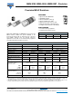
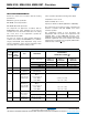
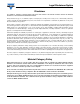
DIMENSIONS
Note
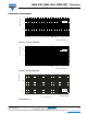
• Color code marking is applied according to IEC 60062
(3)
in five bands. Each color band appears as a single solid line, voids are permissible
if at least
2
/
3
of the band is visible from each radial angle of view. The last color band for tolerance is approximately 50 % wider than the other
bands. An interrupted band between the 4
th
and 5
th
full band indicates the temperature coefficient (yellow = TC25, orange = TC15).
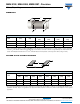
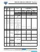
PATTERN STYLES FOR MELF RESISTORS
Note
• The given solder pad dimensions reflect the considerations for board design and assembly as outlined e.g. in standards IEC 61188-5-x, or in
publication IPC-7351. They do not guarantee any supposed thermal properties, however, they will be found adequate for most general
applications.
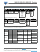
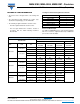
DIMENSIONS AND MASS
TYPE
L
(mm)
D
(mm)
L
1 min.
(mm)
D
1
(mm)
K
(mm)
MASS
(mg)
MMU 0102 2.2 + 0/- 0.1 1.1 + 0/- 0.1 1.2 D + 0/- 0.1 0.4 ± 0.05 8
MMA 0204 3.6 + 0/- 0.2 1.4 + 0/- 0.1 1.8 D + 0/- 0.15 0.8 ± 0.1 22
MMB 0207 5.8 + 0/- 0.15 2.2 + 0/- 0.2 3.2 D + 0/- 0.2 1.15 ± 0.1 80
RECOMMENDED SOLDER PAD DIMENSIONS
TYPE
WAVE SOLDERING REFLOW SOLDERING
G
(mm)
Y
(mm)
X
(mm)
Z
(mm)
G
(mm)
Y
(mm)
X
(mm)
Z
(mm)
MMU 0102 0.7 1.2 1.5 3.1 1.1 0.8 1.3 2.7
MMA 0204 1.5 1.5 1.8 4.5 1.7 1.2 1.6 4.1
MMB 0207 2.8 2.1 2.6 7.0 3.2 1.7 2.4 6.6
L
1
K
D
1
D
L
G
X
Y
Z