
Datasheet


Document Number: 50035
Revision 14-Jan-05
www.vishay.com
18
RTO 50
Vishay Sfernice
For technical questions, contact sfer@vishay.com
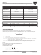
PERFORMANCE
TESTS CONDITIONS TYPICAL DRIFTS
NF EN 140000
Momentary Overload 2Pr/5s ± (0.25% + 0.05Ω)
Us < 1.5UL
NF EN 140000
Rapid Temperature Change CEI 68214 Tests Na ± (0.5% + 0.05Ω)
5 cycles - 55°C to + 155°C
Load Life NF EN 140000 Pr at + 25°C CEI 115_1 ± (1% + 0.05
Ω)
Humidity (Steady State) MIL STD 202 ± (0.5% + 0.05
Ω)
Method 103 B Cond. D
Vibration MIL STD 202 ± (0.2% + 0.05Ω)
Method 204 Cond. D
Terminal Strength MIL STD 202 ± (0.2% + 0.05
Ω)
Method 211 Cond. A1
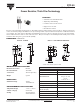
Power Resistor Thick Film Technology
Resistance Values ≥ 0.010Ω ≥ 0.015Ω ≥ 0.1Ω ≥ 0.5Ω
Tolerances ± 1% at ± 10%
Standard ± 900ppm/°C ± 700ppm/°C ± 250ppm/°C ± 150ppm/°C
Temperature
Coefficient
SPECIAL FEATURES
CHOICE OF THE HEATSINK
The user must choose according to the working conditions of the component (power, room temperature).
Maximum working temperature must not exceed 155°C. The dissipated power is simply calculated by the following ratio:
P =
∆T
[RTH (j-c) + RTH (c-a)]
(1)
P: expressed in W
T: difference between maximum working temperature and room temperature.
R
TH: (j-c): thermal resistance value measured between resistive layer and outer side of the resistor. It is the thermal
resistance of the component: (Special Features Table)
R
TH: (c-a): thermal resistance value measured between outer side of the resistor and room temperature. It is the
thermal resistance of the heatsink itself (type, shape) and the quality of the fastening device.
Example:
RTH: (c-a) for RTO 50 power rating 13 W at ambient temperature + 30°C.
Thermal resistance R
TH (j-c): 25°C/W
Considering equation (1) we have:
∆T ≤ 155°C - 30°C ≤ 125°C
RTH (j-c) + RTH (c-a) = = = 9.6°C/W
RTH (c-a)
≤ 9.6°C/W - 2.6°C/W ≤ 7°C/W
∆T
P
125
13