
Datasheet


www.vishay.com
19
RTO 50
Vishay Sfernice
Document Number: 50035
Revision 14-Jan-05
For technical questions, contact sfer@vishay.com
ORDERING INFORMATION
RTO 50 F 100 k� ± 1% xxx
MODEL STYLE CONNECTIONS RESISTANCE VALUE TOLERANCE CUSTOM DESIGN
F: Leaded ± 1% Optional
C: Surface Mount ± 2% on request:
± 5% special TCR,
± 10% shap, etc.
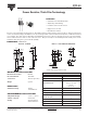
Power Resistor Thick Film Technology
PACKAGING
Tube of 50 units
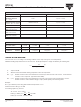
OVERLOADS
The applied voltage must always be lower than the maximum overload voltage of 450V.
The values indicated on the graph below are applicable to resistors in air or mounted onto a heatsink.
10
-6
10
-5
10
-4
10
-3
10
-2
ENERGY IN JOULES
10
1
0.1
0.01
ENERGY CURVE
OVERLOAD DURATION IN SECONDS
POWER RATING CHART
The temperature of the heatsink should be maintained within the limits specified.
To improve the thermal conductivity, surfaces in contact should be coated with a silicone grease and the torque applied on
the screw for tightening should be around 1Nm.
HEATSINK TEMPERATURE IN DEGREES CELSIUS
0 25 40 60 80 100 120 140 155
% RATED POWER
0
25
50
75
100
MARKING
Model, Style, Resistance Value (in ), Tolerance (in %), Manufacturing Date, VISHAY trademark.