
Data Sheet

www.vishay.com For technical questions within your region, please contact one of the following: Document Number: 88715
2 DiodesAmericas@vishay.com
, DiodesAsia@vishay.com, DiodesEurope@vishay.com Revision: 16-Oct-09
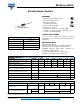
SB120 thru SB160
Vishay General Semiconductor
Note
(1)
Thermal resistance junction to lead P.C.B. mounted 0.375" (9.5 mm) lead length
RATINGS AND CHARACTERISTICS CURVES
(T
A
= 25 °C unless otherwise noted)
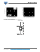
Fig. 1 - Forward Current Derating Curve
Fig. 2 - Maximum Non-Repetitive Peak Forward Surge Current
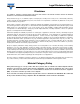
Fig. 3 - Typical Instantaneous Forward Characteristics
Fig. 4 - Typical Reverse Characteristics
THERMAL CHARACTERISTICS (T
A
= 25 °C unless otherwise noted)
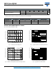
PARAMETER SYMBOL SB120 SB130 SB140 SB150 SB160 UNIT
Typical thermal resistance
R
θJA
(1)
50
°C/W
R
θJL
(1)
15
ORDERING INFORMATION (Example)
PREFERRED P/N UNIT WEIGHT (g) PREFERRED PACKAGE CODE BASE QUANTITY DELIVERY MODE
SB140-E3/54 0.35 54 5500 13" diameter paper tape and reel
SB140-E3/73 0.35 73 3000 Ammo pack packaging
0
0.25
0.5
0.75
0
50 7525
100 125 150
175
1.0
Average Forward Current (A)
Lead Temperature (°C)
Resistive or Inductive Load
0.375" (9.5 mm) Lead Length
SB150 and SB160
SB120 to SB140
0
10
30
20
50
40
1
100
10
Number of Cycles at 60 Hz
Peak Forward Surge Current (A)
T
J
= T
J
Max.
8.3 ms Single Half Sine-Wave
100
10
1
0.1
0.01
0 0.40.2 1.20.80.6 1.4 1.61.0
Instantaneous Forward Voltage (V)
Instantaneous Forward Current (A)
T
J
= 125 °C
T
J
= 25 °C
SB120 thru SB140
SB150 and SB160
T
J
= 150 °C
Pulse Width = 300 μs
1 % Duty Cycle
Instantaneous Reverse Current (mA)
1
10
100
0.01
0.001
0.1
200 10040 60 80
Percent of Rated Peak Reverse Voltage (%)
T
J
= 125 °C
T
J
= 25 °C
T
J
= 75 °C
SB120 thru SB140
SB150 and SB160