
Datasheet

Document Number: 83664 For technical questions, contact: optocoupler.answers@vishay.com
www.vishay.com
Rev. 1.5, 10-Dec-08 603
SFH608
Optocoupler, Phototransistor Output,
Low Input Current, with Base
Connection, 5300 V
RMS
Vishay Semiconductors
Note
T
amb
= 25 °C, unless otherwise specified.
Minimum and maximum values are testing requirements. Typical values are characteristics of the device and are the result of engineering
evaluation. Typical values are for information only and are not part of the testing requirements.
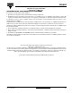
Note
As per IEC 60747-5-2, § 7.4.3.8.1, this optocoupler is suitable for "safe electrical insulation" only within the safety ratings. Compliance with the
safety ratings shall be ensured by means of protective circuits.
COUPLER
Coupling capacitance C
C
0.6 pF
Saturation voltage, collector emitter
I
C
= 0.32 mA, I
F
= 1 mA SFH608-2 V
CEsat
0.25 0.4 V
I
C
= 0.5 mA, I
F
= 1 mA SFH608-3 V
CEsat
0.25 0.4 V
I
C
= 0.8 mA, I
F
= 1 mA SFH608-4 V
CEsat
0.25 0.4 V
I
C
= 1.25 mA, I
F
= 1 mA SFH608-5 V
CEsat
0.25 0.4 V
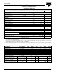
CURRENT TRANSFER RATIO
PARAMETER TEST CONDITION PART SYMBOL MIN. TYP. MAX. UNIT
Coupling transfer ratio
I
F
= 1 mA, V
CC
= 0.5 V SFH608-2 CTR 63 125 %
I
F
= 0.5 mA, V
CC
= 1.5 V SFH608-2 CTR 32 75 %
I
F
= 1 mA, V
CC
= 0.5 V SFH608-3 CTR 100 200 %
I
F
= 0.5 mA, V
CC
= 1.5 V SFH608-3 CTR 50 120 %
I
F
= 1 mA, V
CC
= 0.5 V SFH608-4 CTR 160 320 %
I
F
= 0.5 mA, V
CC
= 1.5 V SFH608-4 CTR 80 200 %
I
F
= 1 mA, V
CC
= 0.5 V SFH608-5 CTR 250 500 %
I
F
= 0.5 mA, V
CC
= 1.5 V SFH608-5 CTR 125 300 %
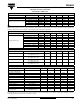
SWITCHING CHARACTERISTICS
PARAMETER TEST CONDITION SYMBOL MIN. TYP. MAX. UNIT
Turn-on time
I
C
= 2 mA (to adjust by I
F
),
R
L
= 100 Ω, V
CC
= 5 V
t
on
8µs
Rise time
I
C
= 2 mA (to adjust by I
F
),
R
L
= 100 Ω, V
CC
= 5 V
t
r
5µs
Turn-off time
I
C
= 2 mA (to adjust by I
F
),
R
L
= 100 Ω, V
CC
= 5 V
t
off
7.5 µs
Fall time
I
C
= 2 mA (to adjust by I
F
),
R
L
= 100 Ω, V
CC
= 5 V
t
f
7µs
SAFETY AND INSULATION RATINGS
PARAMETER TEST CONDITION SYMBOL MIN. TYP. MAX. UNIT
Climatic classification
(according to IEC 68 part 1)
55/100/21
Comparative tracking index CTI 175 399
V
IOTM
8000 V
V
IORM
890 V
P
SO
700 mW
I
SI
400 mA
T
SI
175 °C
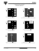
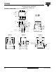
Creepage distance standard DIP-6 7 mm
Clearance distance standard DIP-6 7 mm
Creepage distance 400 mil DIP-6 8 mm
Clearance distance 400 mil DIP-6 8 mm
Insulation thickness,
reinforced rated
per IEC 60950 2.10.5.1 0.4 mm
ELECTRICAL CHARACTERISTICS
PARAMETER TEST CONDITION PART SYMBOL MIN. TYP. MAX. UNIT