
Datasheet

VS-ST230C Series
www.vishay.com
Vishay Semiconductors
Revision: 16-Dec-13
3
Document Number: 94398
For technical questions within your region: DiodesAmericas@vishay.com
, DiodesAsia@vishay.com, DiodesEurope@vishay.com
THIS DOCUMENT IS SUBJECT TO CHANGE WITHOUT NOTICE. THE PRODUCTS DESCRIBED HEREIN AND THIS DOCUMENT
ARE SUBJECT TO SPECIFIC DISCLAIMERS, SET FORTH AT www.vishay.com/doc?91000
Note
• The table above shows the increment of thermal resistance R
thJC
when devices operate at different conduction angles than DC
TRIGGERING
PARAMETER SYMBOL TEST CONDITIONS
VALUES
UNITS
TYP. MAX.
Maximum peak gate power P
GM
T
J
= T
J
maximum, t
p
5 ms 10.0
W
Maximum average gate power P
G(AV)
T
J
= T
J
maximum, f = 50 Hz, d% = 50 2.0
Maximum peak positive gate current I
GM
T
J
= T
J
maximum, t
p
5 ms 3.0 A
Maximum peak positive gate voltage + V
GM
T
J
= T
J
maximum, t
p
5 ms
20
V
Maximum peak negative gate voltage - V
GM
5.0
DC gate current required to trigger I
GT
T
J
= - 40 °C
Maximum required gate trigger/
current/voltage are the lowest
value which will trigger all units
12 V anode to cathode applied
180 -
T
J
= 25 °C 90 150 mA
T
J
= 125 °C 40 -
DC gate voltage required to trigger V
GT
T
J
= - 40 °C 2.9 -
VT
J
= 25 °C 1.8 3.0
T
J
= 125 °C 1.2 -
DC gate current not to trigger I
GD
T
J
= T
J
maximum
Maximum gate current/voltage
not to trigger is the maximum
value which will not trigger any
unit with rated V
DRM
anode to
cathode applied
10 mA
DC gate voltage not to trigger V
GD
0.25 V
THERMAL AND MECHANICAL SPECIFICATIONS
PARAMETER SYMBOL TEST CONDITIONS VALUES UNITS
Maximum operating temperature range T
J
- 40 to 125
°C
Maximum storage temperature range T
Stg
- 40 to 150
Maximum thermal resistance,
junction to heatsink
R
thJ-hs
DC operation single side cooled 0.17
K/W
DC operation double side cooled 0.08
Maximum thermal resistance,
case to heatsink
R
thC-hs
DC operation single side cooled 0.033
DC operation double side cooled 0.017
Mounting force, ± 10 %
4900
(500)
N
(kg)
Approximate weight 50 g
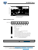
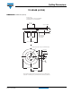
Case style See dimensions - link at the end of datasheet TO-200AB (A-PUK)
R
thJC
CONDUCTION
CONDUCTION ANGLE
SINUSOIDAL CONDUCTION RECTANGULAR CONDUCTION
TEST CONDITIONS UNITS
SINGLE SIDE DOUBLE SIDE SINGLE SIDE DOUBLE SIDE
180° 0.015 0.017 0.011 0.011
T
J
= T
J
maximum K/W
120° 0.018 0.019 0.019 0.019
90° 0.024 0.024 0.026 0.026
60° 0.035 0.035 0.036 0.036
30° 0.060 0.060 0.060 0.061