
Datasheet


TLLE4401, TLLK4401
www.vishay.com
Vishay Semiconductors
Rev. 1.5, 14-Oct-14
1
Document Number: 83343
For technical questions, contact: LED@vishay.com
THIS DOCUMENT IS SUBJECT TO CHANGE WITHOUT NOTICE. THE PRODUCTS DESCRIBED HEREIN AND THIS DOCUMENT
ARE SUBJECT TO SPECIFIC DISCLAIMERS, SET FORTH AT www.vishay.com/doc?91000
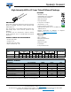
High Intensity LED in Ø 3 mm Tinted Diffused Package
DESCRIPTION
These devices have been designed to meet the increasing
demand for AlInGaP technology general indicating and
lighting purposes.
They are housed in a 3 mm diffused plastic package. The
wide viewing angle of these devices provides a high
brightness.
All packing units are categorized in luminous intensity
groups. That allows users to assemble LEDs with uniform
appearance.
PRODUCT GROUP AND PACKAGE DATA
• Product group: LED
•Package: 3 mm
• Product series: low current
• Angle of half intensity: ± 30°
FEATURES
• AlInGaP technology
• Standard Ø 3 mm (T-1) package
• Small mechanical tolerances
• Wide viewing angle
• Very high intensity
• Low power consumption
• Specified at I
F
= 2 mA
• Luminous intensity categorized
• ESD-withstand voltage: up to 2 kV HBM according to
JESD22-A114-B
• Material categorization: for definitions of compliance
please see www.vishay.com/doc?99912
APPLICATIONS
• Status lights
•Off / on indicator
• Background illumination
• Readout lights
• Maintenance lights
•Legend light
• Low power DC circuits
Note
(1)
Driving the LED in reverse direction is suitable for a short term application
19222
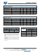
PARTS TABLE
PART COLOR
LUMINOUS INTENSITY
(mcd)
at I
F
(mA)
WAVELENGTH
(nm)
at I
F
(mA)
FORWARD VOLTAGE
(V)
at I
F
(mA)
TECHNOLOGY
MIN. TYP. MAX. MIN. TYP. MAX. MIN. TYP. MAX.
TLLK4401 Super red 6.3 17 32 2 626 630 639 2 1.6 1.8 2.2 2 AllnGaP on GaAs
TLLE4401 Yellow 6.3 17 32 2 581 589 594 2 1.6 1.8 2.2 2 AllnGaP on GaAs
ABSOLUTE MAXIMUM RATINGS (T
amb
= 25 °C, unless otherwise specified)
TLLK4401, TLLE4401
PARAMETER TEST CONDITION SYMBOL VALUE UNIT
Reverse voltage
(1)
V
R
5V
DC forward current T
amb
≤ 60 °C I
F
30 mA
Surge forward current t
p
≤ 10 μs I
FSM
0.1 A
Power dissipation T
amb
≤ 60 °C P
V
80 mW
Junction temperature T
j
100 °C
Operating temperature range T
amb
-40 to +100 °C
Storage temperature range T
stg
-55 to +100 °C
Soldering temperature t ≤ 5 s, 2 mm from body T
sd
260 °C
Thermal resistance junction/ambient R
thJA
400 K/W