
Datasheet

VDRS Series
www.vishay.com
Vishay BCcomponents
Revision: 19-Jun-15
4
Document Number: 29081
For technical questions, contact: nlr@vishay.com
THIS DOCUMENT IS SUBJECT TO CHANGE WITHOUT NOTICE. THE PRODUCTS DESCRIBED HEREIN AND THIS DOCUMENT
ARE SUBJECT TO SPECIFIC DISCLAIMERS, SET FORTH AT www.vishay.com/doc?91000
Notes
(1)
The products are certified according to (c)UL (E332800), VDE (40002622) and CSA (219883)
(2)
The sinusoidal voltage is assumed as the normal operating condition. If a non-sinusoidal voltage is present, type selection should be based on
multiplying the peak voltage by a factor of 0.707.
(3)
The voltage measured at 1 mA meets the requirements of IEC 61051.
The tolerance on the voltage at 1 mA is ± 10 %.
(4)
High energy surges are generally of longer duration. The maximum energy for one pulse of 10 x 1000 μs is given as a reference for longer
duration pulses. This pulse can be characterised by peak current (I
p
) and pulse width t
2
(virtual time of half I
p
value, following IEC 60060-2,
section 6 ). If V
p
is the clamping voltage corresponding to Ip, the energy absorbed in the varistor is determined by the formula:
where:
a) K is dependent on the value of t
2
when the value of t
1
is between 8 μs and 10 μs; see Peak Current as a Function of Pulse Width drawing.
(5)
A current wave of 8 x 20 μs is used as a standard for pulse current and clamping voltage ratings. The maximum non-repetitive transient current
is given for one pulse applied during the life of the component.
(6)
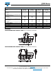
For composition of the SAP part number:
Replace “x” by B for bulk type Replace “y” by S for straight leads
T for tape and reel F for straight leads with flange (bulk only)
A for tape and ammopack G for straight leads with flange and H
0
= 16 mm (tape and reel/ammo)
H for straight leads with flange and H
0
= 18.25 mm (tape and reel/ammo)
K for kinked leads (bulk only)
L for kinked leads with H0 = 16 mm (tape and reel/ammo)
M for kinked leads with H0 = 18.25 mm (tape and reel/ammo)
(7)
All varistors are recognized under VZAC2 surge protective devices, components type 4 as specified in UL 1449 edition 3 for operation in ambient
temperatures up to 85 °C. The parts with indication type 2 or 3 SPD’s, are tested and certified to be used in type 2 or 3 SPD applications with
operating ambient temperatures up to 85 °C. The final acceptance of the component is dependent upon its installation and use in complete
equipment submitted to underwriters laboratories Inc.
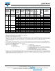
420 560 680
1120 5.0 20.0 400 35 6.1 3.2 ± 0.8 4 VDRS05C420xyE
1120 10.0 56.0 1200 85 6.1 3.2 ± 0.8 4 VDRS07H420xyE
1120 25.0 73.0 2500 165 6.6 3.4 ± 0.8 4 VDRS10P420xyE
1120 50.0 120.0 4500 250 6.6 3.4 ± 0.8 3 VDRS14T420xyE
1120 100.0 344.0 6500 510 8.1 3.7 ± 0.8 2 VDRS20W420ByE
460 615 750
1240 5.0 21.0 400 30 6.4 3.6 ± 0.8 4 VDRS05C460xyE
1240 10.0 63.0 1200 75 6.4 3.6 ± 0.8 4 VDRS07H460xyE
1240 25.0 82.0 2500 150 6.8 3.8 ± 0.8 4 VDRS10P460xyE
1240 50.0 135.0 4500 225 6.8 3.8 ± 0.8 3 VDRS14T460xyE
1240 100.0 360.0 6500 460 8.5 4.1 ± 0.8 2 VDRS20W460ByE
510 670 820
1355 25.0 89.0 2500 135 7.2 4.1 ± 0.8 4 VDRS10P510xyE
1355 50.0 145.0 4500 220 7.2 4.1 ± 0.8 3 VDRS14T510xyE
1355 100.0 376.0 6500 450 8.9 4.4 ± 0.8 2 VDRS20W510ByE
550 745 910
1500 25.0 98.0 2500 120 7.9 4.5 ± 0.8 4 VDRS10P550xyE
1500 50.0 160.0 4500 180 7.9 4.5 ± 0.8 3 VDRS14T550xyE
1500 100.0 408.0 6500 370 9.5 4.9 ± 0.8 2 VDRS20W550ByE
625 825 1000 1650 100.0 448.0 6500 320 10.1 5.3 ± 0.8 2 VDRS20W625ByE
680 895 1100 1815 100.0 496.0 6500 270 10.6 5.8 ± 0.8 2 VDRS20W680ByE
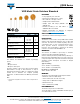
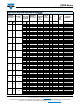
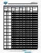
ELECTRICAL DATA AND ORDERING INFORMATION
MAXIMUM
CONTINUOUS
VOLTAGE
VOLTAGE
(3)
at 1 mA
MAXIMUM
VOLTAGE
at STATED
CURRENT
MAXIMUM
ENERGY
(4)
(10 x 1 000 μs)
MAXIMUM
NON-REP.
TRANSIENT
CURRENT
(5)
I
NRP
(8 x 20 μs
)
TYPICAL
CAP.
at 1 kHz
T
(max.)
E
UL 1449
ED3
SPD
TYPE
(7)
CATALOG
NUMBERS
(1)
RMS
(2)
(V)
DC
(V)
(V)
V
(V)
I
(A)
(J) (A) (pF) (mm) (mm) SAP
(6)
EK x V
p
x I
p
x t
2
=