
Datasheet

VDRS Series
www.vishay.com
Vishay BCcomponents
Revision: 19-Jun-15
9
Document Number: 29081
For technical questions, contact: nlr@vishay.com
THIS DOCUMENT IS SUBJECT TO CHANGE WITHOUT NOTICE. THE PRODUCTS DESCRIBED HEREIN AND THIS DOCUMENT
ARE SUBJECT TO SPECIFIC DISCLAIMERS, SET FORTH AT www.vishay.com/doc?91000
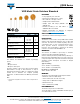
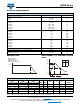
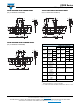
TAPED VERSION WITH KINKED LEADS
(only for VDRS05 and VDRS07)
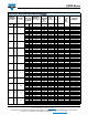
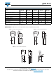
TAPED VERSION WITH FLANGED LEADS
(only for VDRS05 and VDRS07)
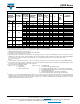
TAPED VERSION WITH KINKED LEADS
(only for VDRS10 and VDRS14)
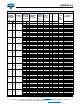
Notes
(1)
Guaranteed between component and tape
(2)
For VDRS14T510xSE and VDRS14T550xSE: H = 20 mm ± 1 mm
T
1
t
T
Δh
Δh
A
0
P
0
P
1
D
0
L
W
0
W
2
W
1
H
0
W
F
d
D
P
Δp
Δp
L
P
0
P
1
D
0
W
0
W
2
W
1
T
1
t
H
0
F
d
D
P
Δp Δp
T
Δh Δh
A
0
W
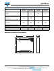
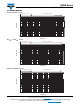
TAPING DATA (based on IEC 60286-2)
SYMBOL PARAMETER
DIMENSIONS/TOLERANCE
VDRS05 VDRS07 VDRS10 VDRS14
A max.
Max.
mounting
height
V
300 V
9.0 11.0
14.5
19.0
V > 300 V 15.0
A
0
max.
Max.
mounting
height
V
320 V
11.0 13.0
16.5 21.0
V > 320 V 17.0 21.5
D max.
Max.
body
diameter
V
320 V
7.0 9.0
12.0 16.0
V > 320 V 12.5 16.5
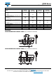
d
Lead wire
diameter
0.6 ± 0.05 0.8 ± 0.05
F
Lead to lead
distance
(1)
5.0 + 0.8/- 0.2 7.5 ± 0.8
H
Distance
component
to tape
center
(2)
20.0 + 2.0/- 0.0 18.0 + 2.0/- 0.0
H
0
Lead wire
clinch height
16.0 or 18.25 ± 0.5
P
Pitch of
components
on tape
12.7 ± 1.0 25.4 ± 1.0
T
Total
thickness
See Electrical Data table
T
Δh
Δh
A
0
T
1
t
P
0
P
1
D
0
F
W
0
W
2
W
1
H
0
W
d
D
P
Δp
Δp