
Datasheet


VDRUS Series
www.vishay.com
Vishay BCcomponents
Revision: 18-Jun-2019
3
Document Number: 29185
For technical questions, contact: nlr@vishay.com
THIS DOCUMENT IS SUBJECT TO CHANGE WITHOUT NOTICE. THE PRODUCTS DESCRIBED HEREIN AND THIS DOCUMENT
ARE SUBJECT TO SPECIFIC DISCLAIMERS, SET FORTH AT www.vishay.com/doc?91000
Notes
(1)
The products are certified according to cULus (E332800), and VDE (40013495). See Agency Approval section on page1 for certificate
download section
(2)
The sinusoidal voltage is assumed as the normal operating condition. If a non-sinusoidal voltage is present, type selection should be based
on multiplying the peak voltage by a factor of 0.707
(3)
The voltage measured at 1 mA meets the requirements of IEC 61051.
The tolerance on the voltage at 1 mA is ± 10 %
(4)
High energy surges are generally of longer duration. The maximum energy for one pulse of 10 x 1000 μs is given as a reference for longer
duration pulses. This pulse can be characterized by peak current (I
p
) and pulse width t
2
(virtual time of half I
p
value). If Vp is the clamping
voltage corresponding to I
p
, the energy absorbed in the varistor is determined by the formula:
where K is dependent on the value of t
2
(see Peak Current as a Function of Pulse Width drawing)
(5)
A current wave of 8 x 20 μs is used as a standard for pulse current and clamping voltage ratings. The maximum non-repetitive transient
current is given for one pulse applied during the life of the component
(6)
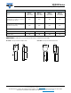
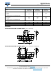
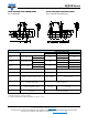
For composition of the SAP part number:
Replace “x” by B for bulk type Replace “y” by S for straight leads
T for tape and reel K for kinked leads (bulk only)
A for tape and ammopack L for kinked leads with H0 = 16 mm (tape and reel/ammo)
M for kinked leads with H0 = 18.25 mm (tape and reel/ammo)
(7)
All varistors are UL1449 edition 4 recognized as SPD type 5 (component level) for operating temperatures up to 125 °C The varistors may
be used in other SPD types as 2, 3, or 4 depending on the indicated nominal discharge current ratings. The final acceptance of the
component is dependent upon its installation and use in complete equipment submitted to Underwriters Laboratories Inc.
350 460 560
920 10.0
55 1800 1
110 5.8 2.7 ± 0.8
VDRUS07M350xyE
920 25.0
113 4500 2
200 7.1 2.9 ± 0.8
VDRUS10T350xyE
920 50.0
240 8000 3
320 6.1 2.9 ± 0.8
VDRUS14X350xyE
920 100.0
475 13 000 5
650 6.5 3.2 ± 0.8
VDRUS20Z350ByE
385 505
620
1025 10.0
59 1800 1
95 6.0 3.0 ± 0.8
VDRUS07M385xyE
1025 25.0
125 4500 2
180 7.5 3.2 ± 0.8
VDRUS10T385xyE
1025 50.0
250 8000 3
280 6.5 3.2 ± 0.8
VDRUS14X385xyE
1025 100.0
490 13 000 5
570 6.8 3.5 ± 0.8
VDRUS20Z385ByE
420 560 680
1120 10.0
62 1800 1
85 6.3 3.2 ± 0.8
VDRUS07M420xyE
1120 25.0
128 4500 2
165 7.7 3.4 ± 0.8
VDRUS10T420xyE
1120 50.0
260 8000 3
250 6.7 3.4 ± 0.8
VDRUS14X420xyE
1120 100.0
500 13 000 5
510 7.1 3.7 ± 0.8
VDRUS20Z420ByE
460 615 750
1290 5.0
66 1800 1
30 6.6 3.6 ± 0.8
VDRUS07M460xyE
1240 25.0
134 4500 2
150 8.0 3.8 ± 0.8
VDRUS10T460xyE
1240 50.0
270 8000 3
225 7.0 3.8 ± 0.8
VDRUS14X460xyE
1240 100.0
525 13 000 5
450 7.5 4.1 ± 0.8
VDRUS20Z460ByE
485 640 780
1290 10.0
68 1800 1
65 6.8 3.7 ± 0.8
VDRUS07M485xyE
1290 25.0
139 4500 2
145 8.3 3.9 ± 0.8
VDRUS10T485xyE
1290 50.0
274 8000 3
220 7.3 3.9 ± 0.8
VDRUS14X485xyE
1290 100.0
530 13 000 5
400 7.6 4.2 ± 0.8
VDRUS20Z485ByE
510
670
820
1355 10.0
71 1800 1
62 7.0 3.9 ± 0.8
VDRUS07M510xyE
1355 25.0
146 4500 2
135 8.5 4.1 ± 0.8
VDRUS10T510xyE
1355 50.0
280 8000 3
220 7.5 4.1 ± 0.8
VDRUS14X510xyE
1355 100.0
545 13 000 5
400 7.9 4.4 ± 0.8
VDRUS20Z510ByE
550 745 910
1500 25.0
152 4500 2
120 8.9 4.5 ± 0.8
VDRUS10T550xyE
1500 50.0
295 8000 3
180 7.9 4.5 ± 0.8
VDRUS14X550xyE
1500 100.0
595 13 000 5
320 8.3 4.9 ± 0.8
VDRUS20Z550ByE
625 825 1000
1650 25.0
170 4500 2
105 9.4 5.0 ± 0.8
VDRUS10T625ByE
1650 50.0
335 8000 3
165 8.4 5.0 ± 0.8
VDRUS14X625ByE
1650 100.0
650 13 000 5
280 8.8 5.3 ± 0.8
VDRUS20Z625ByE
680 895 1100
1815 25.0
180 4500 2
80 10.8 5.4 ± 0.8
VDRUS10T680ByE
1815 50.0
360 8000 3
150 9.8 5.4 ± 0.8
VDRUS14X680ByE
1815 100.0
720 13 000 5
250 10.2 5.8 ± 0.8
VDRUS20Z680ByE
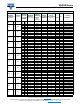
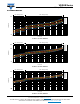
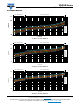
ELECTRICAL DATA AND ORDERING INFORMATION
MAXIMUM
CONTINUOUS
VOLTAGE
VOLTAGE
AT 1 mA
(3)
MAXIMUM
VOLTAGE
AT STATED
CURRENT
MAXIMUM
ENERGY
(4)
(10 x 1000 μs)
MAXIMUM
NON-REP.
TRANSIENT
CURRENT
(5)
I
NRP
(8 x 20 μs)
NOMINAL
DISCHARGE
CURRENT
(7)
TYPICAL
CAPACITANCE
AT 1 kHz
T
(MAX.)
E
CATALOG
NUMBERS
(1)
RMS
(2)
(V)
DC
(V)
(V)
V
(V)
I
(A)
(J) (A) (kA) (pF) (mm) (mm) SAP
(6)
EK x V
p
x I
p
x t
2
=